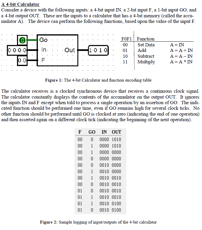

A 4-bit Calculator Consider a device with the following inputs: a 4-bit input IN, a 2-bit input F, a 1-bit input Go, and a 4-bit output OUT. These are the inputs to a calculator that has a 4-bit memory (called the accu- mulator A). The device can perform the following functions, based upon the value of the input F F0F1 Function 0 Go 00 Set Data Out 1.0.1.0 0.0.0.0 In 01 Add 10 Subtract 0-0 11 Multiply A A IN Figure 1: The 4-bit Calculator and function encoding table The calculator receives is a clocked synchronous device that receives a continuous clock signal. The calculator constantly displays the contents of the accumulator on the output OUT. It ignores the inputs IN and F except when told to process a single operation by an assertion of Go. The indi- cated function should be performed one time, even if Go remains high for several clock ticks. No other function should be performed until Go is clocked at zero (indicating the end of one operation) and then asserted again on a different clock tick (indicating the beginning of the next operation). F GO IN OUT 00 0 0000 1010 00 1 0000 1010 00 1 0000 0000 00 0 0000 0000 00 0 0010 0000 00 1 0010 0000 00 1 0010 0010 00 0 0010 0010 01 0 0010 0010 01 1 0010 0010 01 1 0010 0100 01 0 0010 0100 Figure 2: Sample logging of input/outputs of the 4-bit calculator A 4-bit Calculator Consider a device with the following inputs: a 4-bit input IN, a 2-bit input F, a 1-bit input Go, and a 4-bit output OUT. These are the inputs to a calculator that has a 4-bit memory (called the accu- mulator A). The device can perform the following functions, based upon the value of the input F F0F1 Function 0 Go 00 Set Data Out 1.0.1.0 0.0.0.0 In 01 Add 10 Subtract 0-0 11 Multiply A A IN Figure 1: The 4-bit Calculator and function encoding table The calculator receives is a clocked synchronous device that receives a continuous clock signal. The calculator constantly displays the contents of the accumulator on the output OUT. It ignores the inputs IN and F except when told to process a single operation by an assertion of Go. The indi- cated function should be performed one time, even if Go remains high for several clock ticks. No other function should be performed until Go is clocked at zero (indicating the end of one operation) and then asserted again on a different clock tick (indicating the beginning of the next operation). F GO IN OUT 00 0 0000 1010 00 1 0000 1010 00 1 0000 0000 00 0 0000 0000 00 0 0010 0000 00 1 0010 0000 00 1 0010 0010 00 0 0010 0010 01 0 0010 0010 01 1 0010 0010 01 1 0010 0100 01 0 0010 0100 Figure 2: Sample logging of input/outputs of the 4-bit calculator


