Answered step by step
Verified Expert Solution
Question
1 Approved Answer
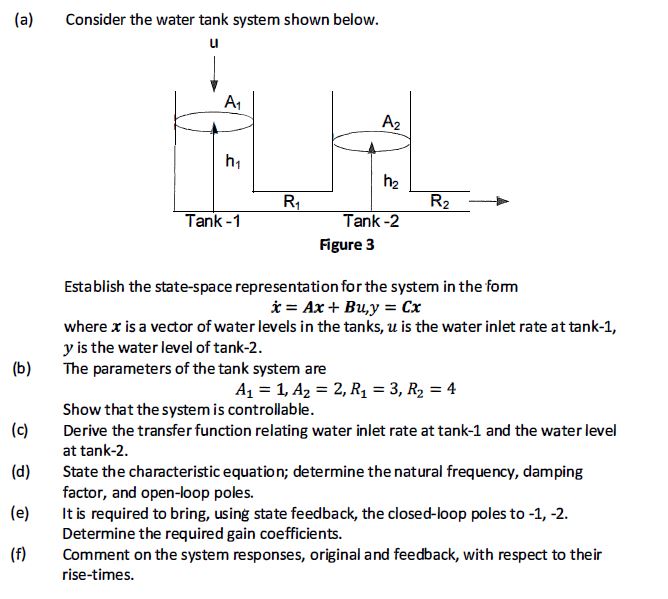
(a) (b) (c) (d) (e) (f) Consider the water tank system shown below. u A A2 h h R R Tank-1 Tank-2 Figure 3

(a) (b) (c) (d) (e) (f) Consider the water tank system shown below. u A A2 h h R R Tank-1 Tank-2 Figure 3 Establish the state-space representation for the system in the form x=Ax+ Bu,y=Cx where x is a vector of water levels in the tanks, u is the water inlet rate at tank-1, y is the water level of tank-2. The parameters of the tank system are A =1, A2 = 2, R = 3, R = 4 Show that the system is controllable. Derive the transfer function relating water inlet rate at tank-1 and the water level at tank-2. State the characteristic equation; determine the natural frequency, damping factor, and open-loop poles. It is required to bring, using state feedback, the closed-loop poles to -1, -2. Determine the required gain coefficients. Comment on the system responses, original and feedback, with respect to their rise-times.
Step by Step Solution
There are 3 Steps involved in it
Step: 1

Get Instant Access to Expert-Tailored Solutions
See step-by-step solutions with expert insights and AI powered tools for academic success
Step: 2

Step: 3

Ace Your Homework with AI
Get the answers you need in no time with our AI-driven, step-by-step assistance
Get Started


