Answered step by step
Verified Expert Solution
Question
1 Approved Answer
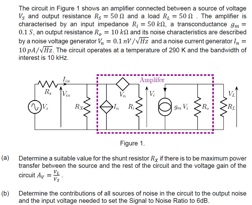
(a) (b) The circuit in Figure 1 shows an amplifier connected between a source of voltage Vs and output resistance R$ 50 and a

(a) (b) The circuit in Figure 1 shows an amplifier connected between a source of voltage Vs and output resistance R$ 50 and a load R 50. The amplifier is characterised by an input impedance R 50 kn, a transconductance Im = 0.1 S, an output resistance Ro = 10 k and its noise characteristics are described by a noise voltage generator V = 0.1 nV/Hz and a noise current generator In = 10 pA/Hz. The circuit operates at a temperature of 290 K and the bandwidth of interest is 10 kHz. Vs I I T I VL Vin Vi RL Rx In Ri *T*T # # Iin - - . Amplifer - V Figure 1. Determine a suitable value for the shunt resistor Rx if there is to be maximum power transfer between the source and the rest of the circuit and the voltage gain of the VL circuit Av Vs Determine the contributions of all sources of noise in the circuit to the output noise and the input voltage needed to set the Signal to Noise Ratio to 6dB.
Step by Step Solution
★★★★★
3.36 Rating (149 Votes )
There are 3 Steps involved in it
Step: 1

Get Instant Access to Expert-Tailored Solutions
See step-by-step solutions with expert insights and AI powered tools for academic success
Step: 2

Step: 3

Ace Your Homework with AI
Get the answers you need in no time with our AI-driven, step-by-step assistance
Get Started


