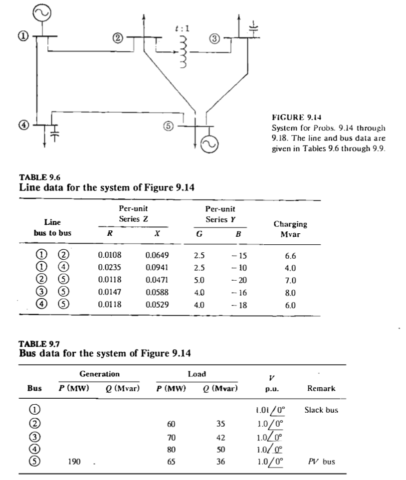
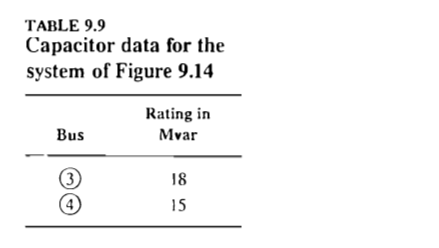
A five-bus power system is shown in Fig. 9.14. The line, bus, transformer, and capacitor data are given in Tables 9.6, 9.7, 9.8, and 9.9,
A five-bus power system is shown in Fig. 9.14. The line, bus, transformer, and capacitor data are given in Tables 9.6, 9.7, 9.8, and 9.9, respectively. Use the Gauss-Seidel method to find the bus voltages for the first iteration.


Line bus to bus TABLE 9.6 Line data for the system of Figure 9.14 @3* (1) (2) 2 3 (4 Bus P (MW) (5) ote at R 190 Per-unit Series Z 0.0108 0.0235 0.0118 0.0147 0.0118 Generation TABLE 9.7 Bus data for the system of Figure 9.14 X 0.0649 0.0941 0.0471 t:1 0.0588 0.0529 Q (Mvar) P (MW) 60 70 80 65 G Per-unit Series Y 2.5 2.5 5.0 4.0 4.0 Load B 35 42 50 36 - 15 - 10 - 20 - 16 - 18 Q (Mvar) FIGURE 9.14 System for Probs. 9.14 through 9.18. The line and bus data are given in Tables 9.6 through 9.9. Charging Mvar V p.u. 6.6 4.0 7.0 8.0 6.0 1.01/0 1.0/0 1.0/0 1.0/0 1.0/0 Remark Slack bus PV bus TABLE 9.8 Transformer data for the system of Figure 9.14 Transformer bus to bus 2 Per-unit reactance 0.04 Tap setting 0.975 TABLE 9.9 Capacitor data for the system of Figure 9.14 Bus (3) 4 Rating in Mvar 18 15
Step by Step Solution
3.38 Rating (154 Votes )
There are 3 Steps involved in it
Step: 1

See step-by-step solutions with expert insights and AI powered tools for academic success
Step: 2

Step: 3

Ace Your Homework with AI
Get the answers you need in no time with our AI-driven, step-by-step assistance
Get Started


