A moment diagram shows the variation of the internal bending moment at each location within a beam as a result of static (non-moving) loads.


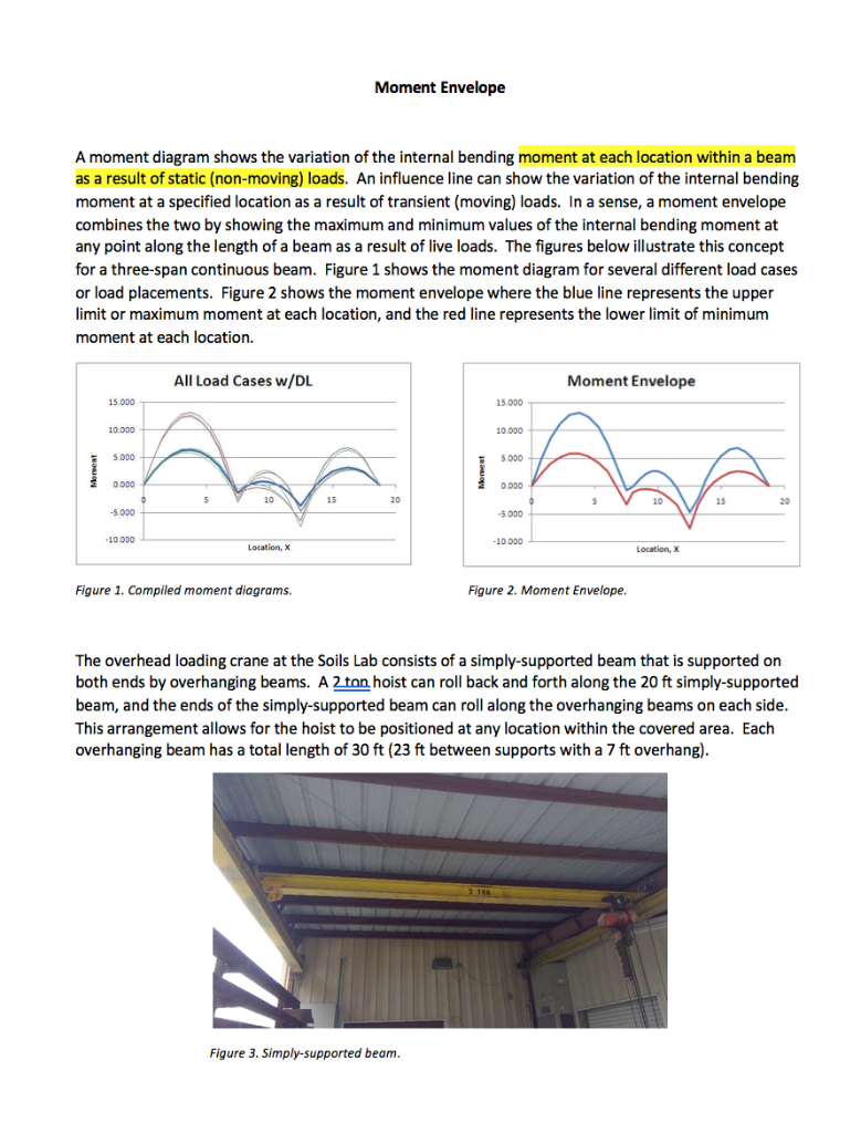
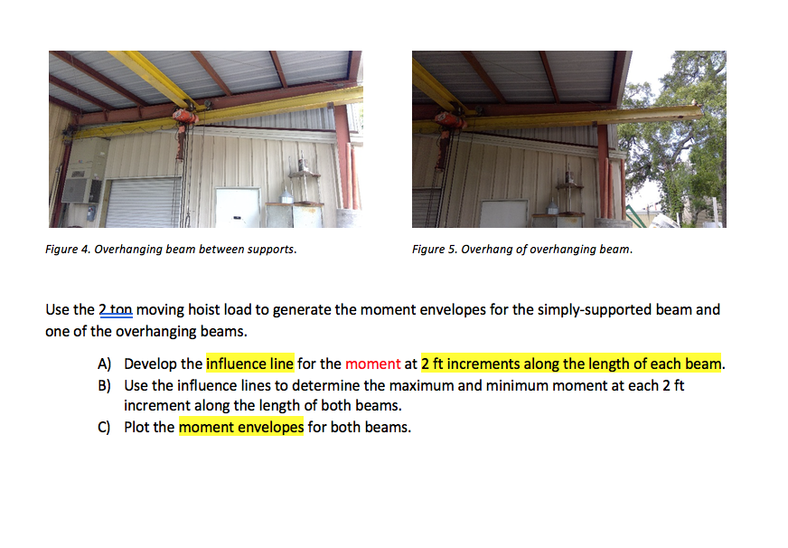
A moment diagram shows the variation of the internal bending moment at each location within a beam as a result of static (non-moving) loads. An influence line can show the variation of the internal bending moment at a specified location as a result of transient (moving) loads. In a sense, a moment envelope combines the two by showing the maximum and minimum values of the internal bending moment at any point along the length of a beam as a result of live loads. The figures below illustrate this concept for a three-span continuous beam. Figure 1 shows the moment diagram for several different load cases or load placements. Figure 2 shows the moment envelope where the blue line represents the upper limit or maximum moment at each location, and the red line represents the lower limit of minimum moment at each location. 15.000 10.000 5.000 0.000 -5.000 -10.000 All Load Cases w/DL 5 10 Location, X Figure 1. Compiled moment diagrams. Moment Envelope 15 20 Figure 3. Simply-supported beam. 15.000 2 TOR 10.000 AA 10 5.000 0.000 -5.000 Moment Envelope -10.000 Figure 2. Moment Envelope. Location, X 15 The overhead loading crane at the Soils Lab consists of a simply-supported beam that is supported on both ends by overhanging beams. A 2 ton hoist can roll back and forth along the 20 ft simply-supported beam, and the ends of the simply-supported beam can roll along the overhanging beams on each side. This arrangement allows for the hoist to be positioned at any location within the covered area. Each overhanging beam has a total length of 30 ft (23 ft between supports with a 7 ft overhang). 20 Figure 4. Overhanging beam between supports. Figure 5. Overhang of overhanging beam. Use the 2 ton moving hoist load to generate the moment envelopes for the simply-supported beam and one of the overhanging beams. A) Develop the influence line for the moment at 2 ft increments along the length of each beam. Use the influence lines to determine the maximum and minimum moment at each 2 ft increment along the length of both beams. B) C) Plot the moment envelopes for both beams.
Step by Step Solution
There are 3 Steps involved in it
Step: 1
To address the given problem we will need to consider the structures shown in the imagesnamely a simplysupported beam with an overhang on both endsas well as the stated moving load of 2 tons which is ...
See step-by-step solutions with expert insights and AI powered tools for academic success
Step: 2

Step: 3

Ace Your Homework with AI
Get the answers you need in no time with our AI-driven, step-by-step assistance
Get Started


