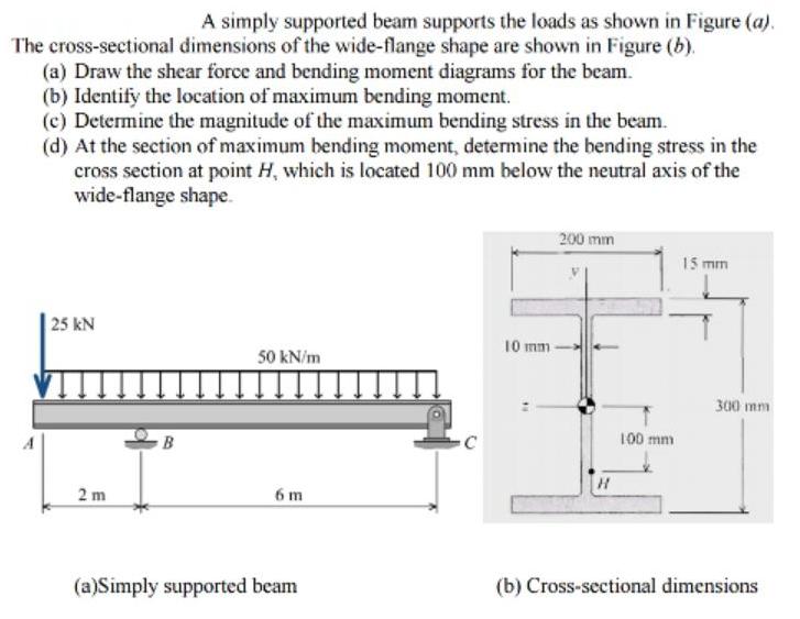
A simply supported beam supports the loads as shown in Figure (a). The cross-sectional dimensions of the wide-flange shape are shown in Figure (b).

A simply supported beam supports the loads as shown in Figure (a). The cross-sectional dimensions of the wide-flange shape are shown in Figure (b). (a) Draw the shear force and bending moment diagrams for the beam. (b) Identify the location of maximum bending moment. (c) Determine the magnitude of the maximum bending stress in the beam. (d) At the section of maximum bending moment, determine the bending stress in the cross section at point H, which is located 100 mm below the neutral axis of the wide-flange shape. 200 mm 15 mm | 25 kN 10 mm - 50 kN/m 300 mm B 100 mm 2 m 6 m (a)Simply supported beam (b) Cross-sectional dimensions
Step by Step Solution
3.55 Rating (152 Votes )
There are 3 Steps involved in it
Step: 1
R5KN SokNm NA Fer Support reachion RA Re 25 SOKB E 425 kN Rex6 25x8 50x8 x40 RB 300 ...
See step-by-step solutions with expert insights and AI powered tools for academic success
Step: 2

Step: 3

Ace Your Homework with AI
Get the answers you need in no time with our AI-driven, step-by-step assistance
Get Started


