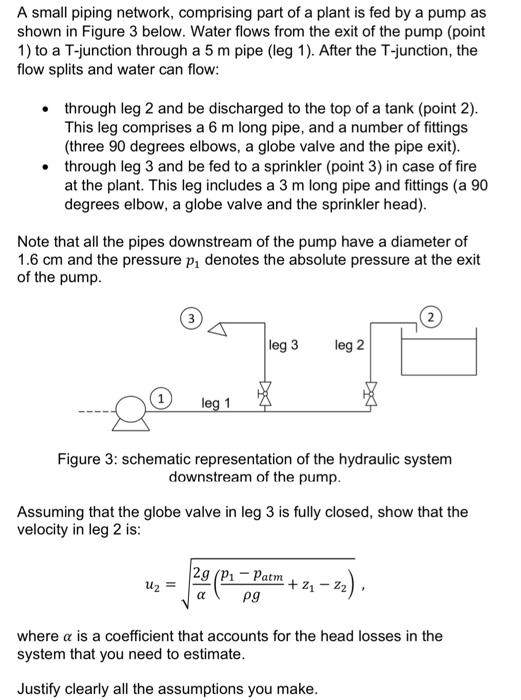
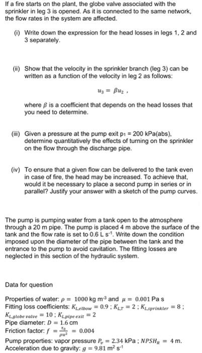
A small piping network, comprising part of a plant is fed by a pump as shown in Figure 3 below. Water flows from the exit of the pump (point 1) to a T-junction through a 5m pipe (leg 1 ). After the T-junction, the flow splits and water can flow: - through leg 2 and be discharged to the top of a tank (point 2). This leg comprises a 6m long pipe, and a number of fittings (three 90 degrees elbows, a globe valve and the pipe exit). - through leg 3 and be fed to a sprinkler (point 3 ) in case of fire at the plant. This leg includes a 3m long pipe and fittings (a 90 degrees elbow, a globe valve and the sprinkler head). Note that all the pipes downstream of the pump have a diameter of 1.6cm and the pressure p1 denotes the absolute pressure at the exit of the pump. Figure 3: schematic representation of the hydraulic system downstream of the pump. Assuming that the globe valve in leg 3 is fully closed, show that the velocity in leg 2 is: u2=2g(gp1patm+z1z2), where is a coefficient that accounts for the head losses in the system that you need to estimate. Justify clearly all the assumptions you make. If a fire starts on the plant, the globe valve associated with the sprinkler in leg 3 is opened. As it is connected to the same network, the flow rates in the system are affected. (i) Write down the expression for the head losses in legs 1,2 and 3 separately. (ii) Show that the velocity in the sprinkler branch (leg 3 ) can be written as a function of the velocity in leg 2 as follows: u3=u2, where is a coefficient that depends on the head losses that you need to determine. (iii) Given a pressure at the pump exit p1=200kPa (abs), determine quantitatively the effects of turning on the sprinkler on the flow through the discharge pipe. (iv) To ensure that a given flow can be delivered to the tank even in case of fire, the head may be increased. To achieve that, would it be necessary to place a second pump in series or in parallel? Justify your answer with a sketch of the pump curves. The pump is pumping water from a tank open to the atmosphere through a 20m pipe. The pump is placed 4m above the surface of the tank and the flow rate is set to 0.6Lss1. Write down the condition imposed upon the diameter of the pipe between the tank and the entrance to the pump to avoid cavitation. The fitting losses are neglected in this section of the hydraulic system. Data for question Properties of water: =1000kgm3 and =0.001Pas Fitting loss coefficients: KLeelbow=0.9;KL,T=2;KL,sprinkler=8; KLglobevalve=10;KL,pipeexit=2 Pipe diameter: D=1.6cm Friction factor: f=u20=0.004 Pump properties: vapor pressure Pv=2.34kPa;NPSHR=4m. Acceleration due to gravity: g=9.81m2s1


