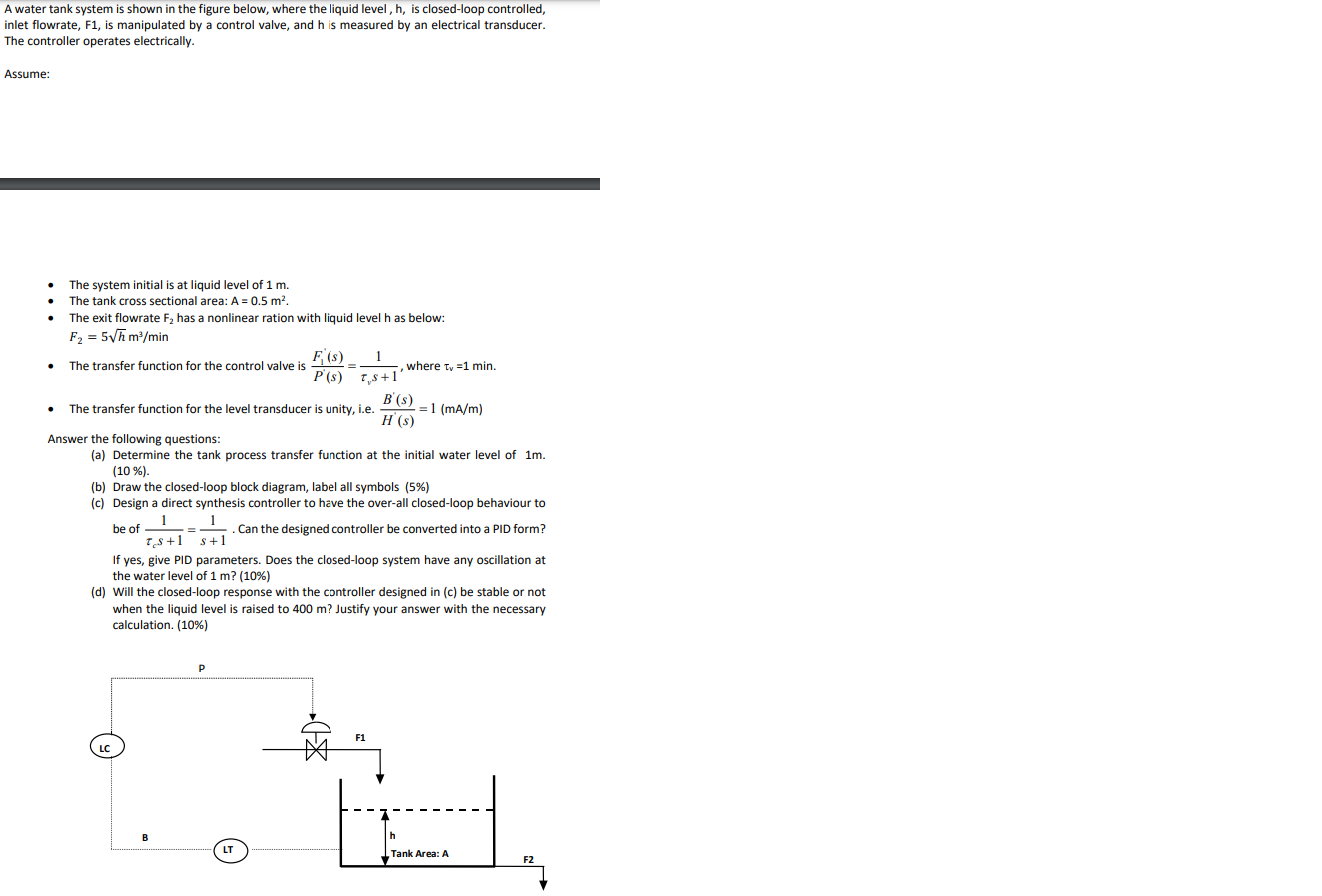
A water tank system is shown in the figure below, where the liquid level, h, is closed-loop controlled, inlet flowrate, F1, is manipulated by a control valve, and h is measured by an electrical transducer. The controller operates electrically. Assume: - The system initial is at liquid level of 1m. - The tank cross sectional area: A=0.5m2. - The exit flowrate F2 has a nonlinear ration with liquid level h as below: F2=5hm3/min - The transfer function for the control valve is P(s)F1(s)=vs+11, where v=1min. - The transfer function for the level transducer is unity, i.e. H(s)B(s)=1(mA/m) Answer the following questions: (a) Determine the tank process transfer function at the initial water level of 1m. (10%) (b) Draw the closed-loop block diagram, label all symbols (5\%) (c) Design a direct synthesis controller to have the over-all closed-loop behaviour to be of cs+11=s+11. Can the designed controller be converted into a PID form? If yes, give PID parameters. Does the closed-loop system have any oscillation at the water level of 1m ? (10\%) (d) Will the closed-loop response with the controller designed in (c) be stable or not when the liquid level is raised to 400m ? Justify your answer with the necessary calculation. (10\%) A water tank system is shown in the figure below, where the liquid level, h, is closed-loop controlled, inlet flowrate, F1, is manipulated by a control valve, and h is measured by an electrical transducer. The controller operates electrically. Assume: - The system initial is at liquid level of 1m. - The tank cross sectional area: A=0.5m2. - The exit flowrate F2 has a nonlinear ration with liquid level h as below: F2=5hm3/min - The transfer function for the control valve is P(s)F1(s)=vs+11, where v=1min. - The transfer function for the level transducer is unity, i.e. H(s)B(s)=1(mA/m) Answer the following questions: (a) Determine the tank process transfer function at the initial water level of 1m. (10%) (b) Draw the closed-loop block diagram, label all symbols (5\%) (c) Design a direct synthesis controller to have the over-all closed-loop behaviour to be of cs+11=s+11. Can the designed controller be converted into a PID form? If yes, give PID parameters. Does the closed-loop system have any oscillation at the water level of 1m ? (10\%) (d) Will the closed-loop response with the controller designed in (c) be stable or not when the liquid level is raised to 400m ? Justify your answer with the necessary calculation. (10\%)