Answered step by step
Verified Expert Solution
Question
1 Approved Answer
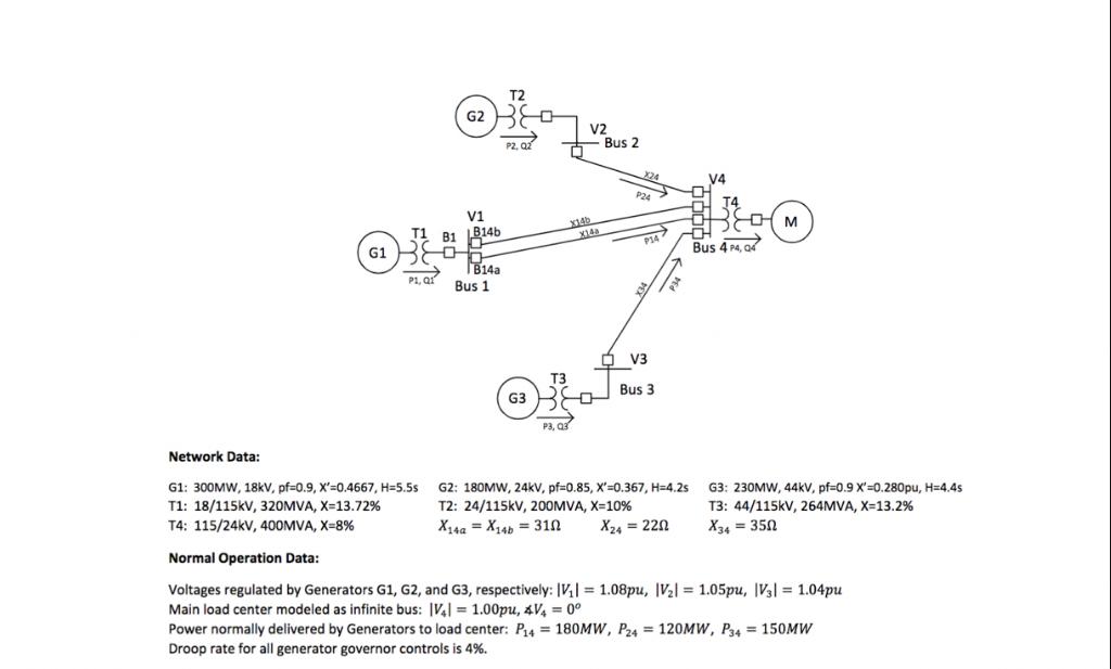
a) What is the internal voltage of Generator G1? |E|=?pu If a fault occurs on Bus 1 or on both Lines L14a and L14b,


a) What is the internal voltage of Generator G1? |E|=?pu If a fault occurs on Bus 1 or on both Lines L14a and L14b, (1) what is the critical clearing angle, 8cr =? (2) what is the critical clearing time, ter =? b) Design a protection scheme for Generator G1 against the faults on the transmission network, ensuring that the generator is in stable operation during and after the fault. Use power common base = 500MVA for the above transient stability control calculations. Project Group 1: X14a X14b 28.00 X24 = 19.00 X34 = 32.00 AP 198MW Network Data: G1 T1 P1, QI G1: 300MW, 18kV, pf=0.9, X'=0.4667, H=5.5s T1: 18/115kV, 320MVA, X=13.72% T4: 115/24kV, 400MVA, X=8% T2 G20 P2, Qz V1 LB14b OR B14a Bus 1 G3 T3 X14b V2 S P3, Q3 X14a Bus 2 P24> P14 $ V3 Bus 3 G2: 180MW, 24kV, pf=0.85, X'=0.367, H=4.2s T2: 24/115kV, 200MVA, X=10% X14a X14b = 310 X24 = 220 V4 Bus 4 P4, 04 M G3: 230MW, 44kV, pf=0.9 X'=0.280pu, H=4.4s T3: 44/115kV, 264MVA, X=13.2% X34 = 350 Normal Operation Data: Voltages regulated by Generators G1, G2, and G3, respectively: IV|= 1.08pu, |V|= 1.05pu, |V3|= 1.04pu Main load center modeled as infinite bus: |V4|= 1.00pu, 4V = 0 Power normally delivered by Generators to load center: P14 = 180MW, P24 = 120MW, P34 = 150MW Droop rate for all generator governor controls is 4%.
Step by Step Solution
★★★★★
3.53 Rating (153 Votes )
There are 3 Steps involved in it
Step: 1

Get Instant Access to Expert-Tailored Solutions
See step-by-step solutions with expert insights and AI powered tools for academic success
Step: 2

Step: 3

Ace Your Homework with AI
Get the answers you need in no time with our AI-driven, step-by-step assistance
Get Started


