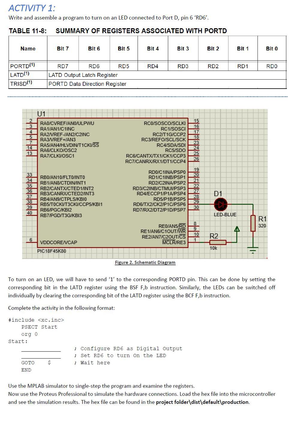
ACTIVITY 1: Write and assemble a program to turn on an LED connected to Port D, pin 6 'RD6'. TABLE 11-8: SUMMARY OF REGISTERS ASSOCIATED WITH PORTD Name Bit 7 Bit 6 Bit 5 Bit 4 Bit 3 Bit 2 Bit 1 Bit 0 RD4 RD3 RD2 RD1 RDO PORTD(1) LATD(1) TRISD(1) RD7 RD6 RD5 LATD Output Latch Register PORTD Data Direction Register U1 2 3 4 RAD/CVREFAN0/ULPWU RA1/AN1/C1INC RA2/VREF-IAN2/C2INC RA3/VREF+IAN3 RAS/AN/HLVDIN/T1CKI/SS RA6/CLKO/OSC2 RA7/CLKI/OSC1 RCO/SOSCO/SCLKI RC1/SOSCI RC2/T1G/CCP2 RC3/REFO/SCU/SCK RC4/SDA/SDI RC5/SDO RC6/CANTX/TX1/CK1/CCP3 RC7/CANRX/RX1/DT1/CCP4 15 16 17 18 23 24 25 26 7 14 13 33 34 35 36 37 38 39 40 RBO/AN10/FLTO/INTO RB1/ANS/CTDININT1 RB2/CANTX/CTED 1/INT2 RB3/CANRXICTED2/INT3 RB4/AN9/CTPLS/KBIO RBS/TOCKI/T3CKI/CCP5/KBI1 RB6/PGC/KBI2 RB7/PGD/T3G/KBI3 RDO/C1INA/PSPO RD1/C1INB/PSP1 RD2/C2INA/PSP2 RD3/C2INB/CTMUV/PSP3 RD4/ECCP1/P1A/PSP4 RD5/P1B/PSP5 RD6/TX2/CK2/P1C/PSP6 RD7/RX2/DT2/P1D/PSP7 19 20 21 22 27 28 29 30 D1 LED-BLUE REO/ANSIRDS R1 320 d RE1/AN6/C1OUTWR REZIAN7/C2OUT/CS MCLR/RE3 10 R2 6 VDDCORE/CAP PIC18F45K80 10K Figure 2. Schematic Diagram To turn on an LED, we will have to send '1' to the corresponding PORTD pin. This can be done by setting the corresponding bit in the LATD register using the BSF F,b instruction. Similarly, the LEDs can be switched off individually by clearing the corresponding bit of the LATD register using the BCF F,b instruction. Complete the activity in the following format: #include
PSECT Start Org 0 Start: ; Configure RD6 as Digital Output ; Set RD6 to turn on the LED ; Wait here $ GOTO END Use the MPLAB simulator to single-step the program and examine the registers. Now use the Proteus Professional to simulate the hardware connections. Load the hex file into the microcontroller and see the simulation results. The hex file can be found in the project folder\dist\default\production. ACTIVITY 1: Write and assemble a program to turn on an LED connected to Port D, pin 6 'RD6'. TABLE 11-8: SUMMARY OF REGISTERS ASSOCIATED WITH PORTD Name Bit 7 Bit 6 Bit 5 Bit 4 Bit 3 Bit 2 Bit 1 Bit 0 RD4 RD3 RD2 RD1 RDO PORTD(1) LATD(1) TRISD(1) RD7 RD6 RD5 LATD Output Latch Register PORTD Data Direction Register U1 2 3 4 RAD/CVREFAN0/ULPWU RA1/AN1/C1INC RA2/VREF-IAN2/C2INC RA3/VREF+IAN3 RAS/AN/HLVDIN/T1CKI/SS RA6/CLKO/OSC2 RA7/CLKI/OSC1 RCO/SOSCO/SCLKI RC1/SOSCI RC2/T1G/CCP2 RC3/REFO/SCU/SCK RC4/SDA/SDI RC5/SDO RC6/CANTX/TX1/CK1/CCP3 RC7/CANRX/RX1/DT1/CCP4 15 16 17 18 23 24 25 26 7 14 13 33 34 35 36 37 38 39 40 RBO/AN10/FLTO/INTO RB1/ANS/CTDININT1 RB2/CANTX/CTED 1/INT2 RB3/CANRXICTED2/INT3 RB4/AN9/CTPLS/KBIO RBS/TOCKI/T3CKI/CCP5/KBI1 RB6/PGC/KBI2 RB7/PGD/T3G/KBI3 RDO/C1INA/PSPO RD1/C1INB/PSP1 RD2/C2INA/PSP2 RD3/C2INB/CTMUV/PSP3 RD4/ECCP1/P1A/PSP4 RD5/P1B/PSP5 RD6/TX2/CK2/P1C/PSP6 RD7/RX2/DT2/P1D/PSP7 19 20 21 22 27 28 29 30 D1 LED-BLUE REO/ANSIRDS R1 320 d RE1/AN6/C1OUTWR REZIAN7/C2OUT/CS MCLR/RE3 10 R2 6 VDDCORE/CAP PIC18F45K80 10K Figure 2. Schematic Diagram To turn on an LED, we will have to send '1' to the corresponding PORTD pin. This can be done by setting the corresponding bit in the LATD register using the BSF F,b instruction. Similarly, the LEDs can be switched off individually by clearing the corresponding bit of the LATD register using the BCF F,b instruction. Complete the activity in the following format: #include PSECT Start Org 0 Start: ; Configure RD6 as Digital Output ; Set RD6 to turn on the LED ; Wait here $ GOTO END Use the MPLAB simulator to single-step the program and examine the registers. Now use the Proteus Professional to simulate the hardware connections. Load the hex file into the microcontroller and see the simulation results. The hex file can be found in the project folder\dist\default\production