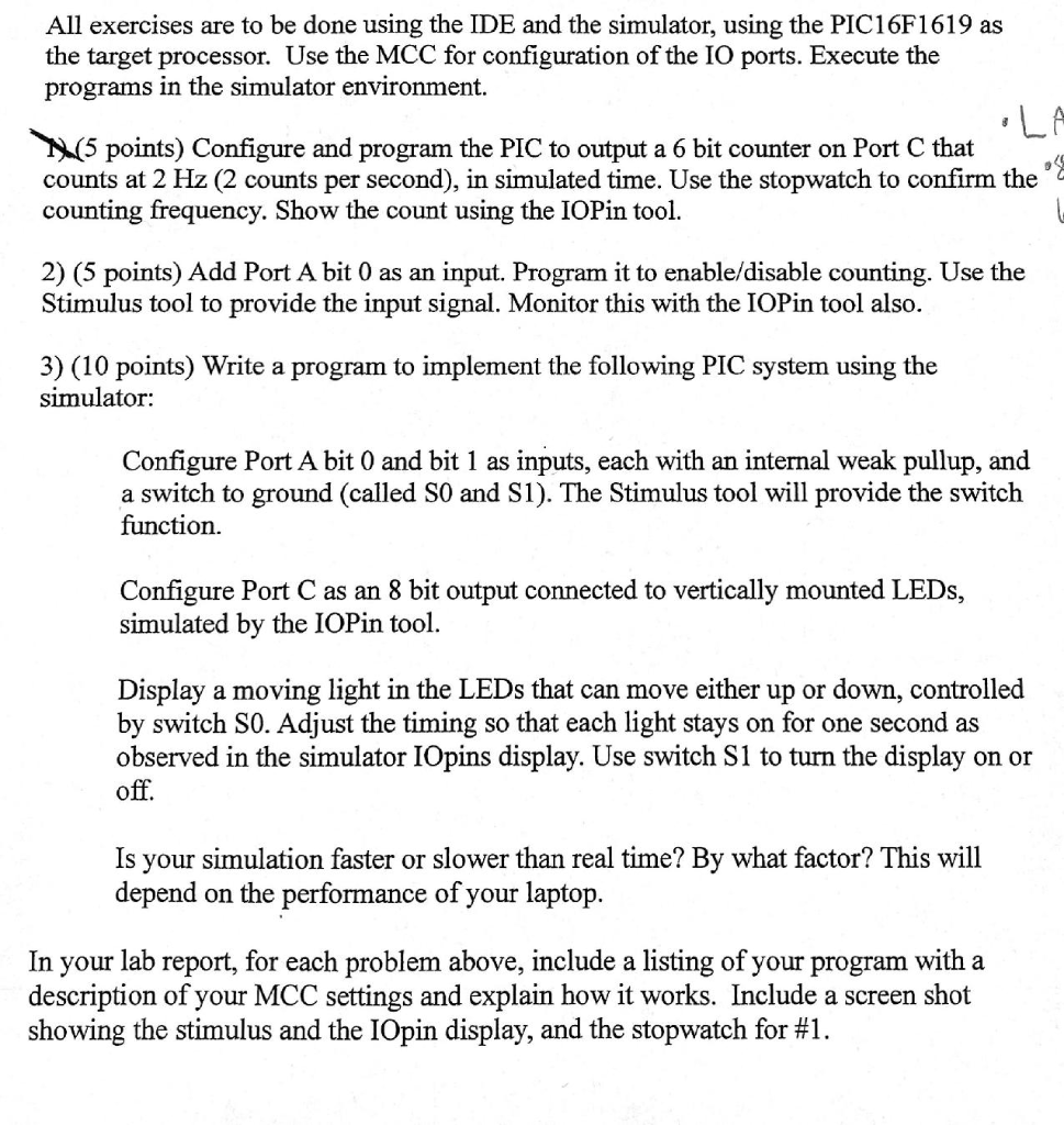
All exercises are to be done using the IDE and the simulator, using the PIC16F1619 as the target processor. Use the MCC for configuration of the IO ports. Execute the programs in the simulator environment. (5 points) Configure and program the PIC to output a 6 bit counter on Port C that counts at 2 Hz (2 counts per second), in simulated time. Use the stopwatch to confirm the counting frequency. Show the count using the IOPin tool. 2) (5 points) Add Port A bit 0 as an input. Program it to enable/disable counting. Use the Stimulus tool to provide the input signal. Monitor this with the IOPin tool also. 3) (10 points) Write a program to implement the following PIC system using the simulator: Configure Port A bit 0 and bit 1 as inputs, each with an internal weak pullup, and a switch to ground (called SO and S1). The Stimulus tool will provide the switch function. Configure Port C as an 8 bit output connected to vertically mounted LEDs, simulated by the IOPin tool. Display a moving light in the LEDs that can move either up or down, controlled by switch SO. Adjust the timing so that each light stays on for one second as observed in the simulator IOpins display. Use switch S1 to turn the display on or off. Is your simulation faster or slower than real time? By what factor? This will depend on the performance of your laptop. In your lab report, for each problem above, include a listing of your program with a description of your MCC settings and explain how it works. Include a screen shot showing the stimulus and the IOpin display, and the stopwatch for #1. All exercises are to be done using the IDE and the simulator, using the PIC16F1619 as the target processor. Use the MCC for configuration of the IO ports. Execute the programs in the simulator environment. (5 points) Configure and program the PIC to output a 6 bit counter on Port C that counts at 2 Hz (2 counts per second), in simulated time. Use the stopwatch to confirm the counting frequency. Show the count using the IOPin tool. 2) (5 points) Add Port A bit 0 as an input. Program it to enable/disable counting. Use the Stimulus tool to provide the input signal. Monitor this with the IOPin tool also. 3) (10 points) Write a program to implement the following PIC system using the simulator: Configure Port A bit 0 and bit 1 as inputs, each with an internal weak pullup, and a switch to ground (called SO and S1). The Stimulus tool will provide the switch function. Configure Port C as an 8 bit output connected to vertically mounted LEDs, simulated by the IOPin tool. Display a moving light in the LEDs that can move either up or down, controlled by switch SO. Adjust the timing so that each light stays on for one second as observed in the simulator IOpins display. Use switch S1 to turn the display on or off. Is your simulation faster or slower than real time? By what factor? This will depend on the performance of your laptop. In your lab report, for each problem above, include a listing of your program with a description of your MCC settings and explain how it works. Include a screen shot showing the stimulus and the IOpin display, and the stopwatch for #1


