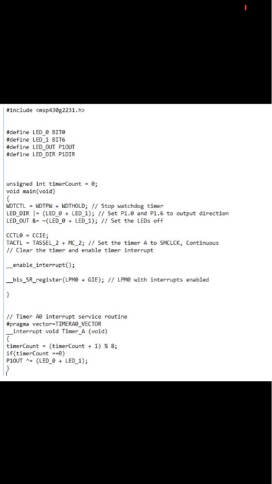
Part 2: Variable Blinking LEDs Using Interrupts Create a C program that runs on the MSP430 that will blink LED1 (port 1 pin 0) at a rate of exactly 1 Hz (meaning one cycle per second). The LED should be on for a fraction x of the cycle and off for a fraction 1-x of the cycle. Select two values of x between and specify your choice 1. 2. Start with your program in part 2.1 and create a C program that runs on the MSP430 that will execute an interrupt subroutine in response to pushing button P1.1 and as a result increases the rate at which LEDI (port 1 pin 0) blinks. Your program should increase the rate at which LEDI blinks for 4 button presses. On the fifth button press the program should reset the LED1 blinlk rate to 1 Hz Lab Questions Use any of our documents (textbook, family user guide or datasheet) to answer the following questions. For each answer, state the document and the page number where you obtained your answer a) What does the term vectored interrupts mean? b) Locate the interrupt vector table. What is the vector address and priority number for port 1 (where c) d) the push button belongs) and for the watchdog timer? What are all the non-maskable interrupts for our microcontroller? What does bouncing mean? What is one way to address it? Deliverables Answers to lab questions 2.a-d uploaded to UTCLearn. A flowchart of your programs for parts 2.1 and 2.2 uploaded to UTCLearn Commented source code for parts 2.1 and 2.2 uploaded to UTCLearn. Analysis proving that your code in part 2.1 blinks the LED at the specified rates. This must involve a calculation including instruction cycle counts and your board's clock frequency Resources Required: TI MSP430FR6989 Launchpad and the IAR Embedded Workbench Integrated Design Environment MSP430 Microcontroller Basics by John Davies, Newnes, 2008. ISBN: 978-0-7506-8276-3 MSP430FRxx Family: User's Guide by Texas Instruments. Part 2: Variable Blinking LEDs Using Interrupts Create a C program that runs on the MSP430 that will blink LED1 (port 1 pin 0) at a rate of exactly 1 Hz (meaning one cycle per second). The LED should be on for a fraction x of the cycle and off for a fraction 1-x of the cycle. Select two values of x between and specify your choice 1. 2. Start with your program in part 2.1 and create a C program that runs on the MSP430 that will execute an interrupt subroutine in response to pushing button P1.1 and as a result increases the rate at which LEDI (port 1 pin 0) blinks. Your program should increase the rate at which LEDI blinks for 4 button presses. On the fifth button press the program should reset the LED1 blinlk rate to 1 Hz Lab Questions Use any of our documents (textbook, family user guide or datasheet) to answer the following questions. For each answer, state the document and the page number where you obtained your answer a) What does the term vectored interrupts mean? b) Locate the interrupt vector table. What is the vector address and priority number for port 1 (where c) d) the push button belongs) and for the watchdog timer? What are all the non-maskable interrupts for our microcontroller? What does bouncing mean? What is one way to address it? Deliverables Answers to lab questions 2.a-d uploaded to UTCLearn. A flowchart of your programs for parts 2.1 and 2.2 uploaded to UTCLearn Commented source code for parts 2.1 and 2.2 uploaded to UTCLearn. Analysis proving that your code in part 2.1 blinks the LED at the specified rates. This must involve a calculation including instruction cycle counts and your board's clock frequency Resources Required: TI MSP430FR6989 Launchpad and the IAR Embedded Workbench Integrated Design Environment MSP430 Microcontroller Basics by John Davies, Newnes, 2008. ISBN: 978-0-7506-8276-3 MSP430FRxx Family: User's Guide by Texas Instruments