Answered step by step
Verified Expert Solution
Question
1 Approved Answer
Develop a simulation of a Light Detector using Tinkercad. The LCD will display the INPUT 10- bit Value received from Photo resistor and OUTPUT

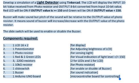
Develop a simulation of a Light Detector using Tinkercad. The LCD will display the INPUT 10- bit Value received from Photo resistor and OUTPUT 8-bit converted from Input 10-bit value. Red LED will be ON if OUTPUT value is >= 150 and Green will be ON if OUTPUT value < 150. Buzzer will make sound but pitch of the sound will be relative to the OUTPUT value of photo resistor. It means sound of buzzer will increase/decrease with the OUTPUT value of the photo resistor. The slide switch will be used to enable or disable the Buzzer. Components required: 1 LCD 16 x 2 1 Potentiometer 1 Photo resistor 1 Red & 1 Green LEDs 1. 2. 3. 4. 5. 6. 6. 7. 6. 3, 2200 resistors 1 10k0 resistor 1 slideswitch 1 Buzzer 1 Arduino UNO board [for display] [for Adjusting brightness of LCD] [for sensing Light] [for Visual indication of light level >/
Step by Step Solution
★★★★★
3.38 Rating (148 Votes )
There are 3 Steps involved in it
Step: 1
To create the simulation of a Light Detector using Tinkercad follow these steps 1 Set up the compone...
Get Instant Access to Expert-Tailored Solutions
See step-by-step solutions with expert insights and AI powered tools for academic success
Step: 2

Step: 3

Ace Your Homework with AI
Get the answers you need in no time with our AI-driven, step-by-step assistance
Get Started


