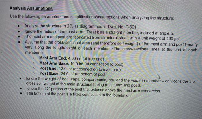
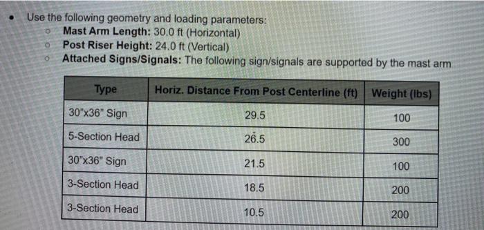
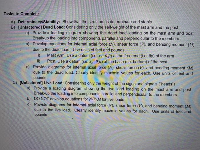
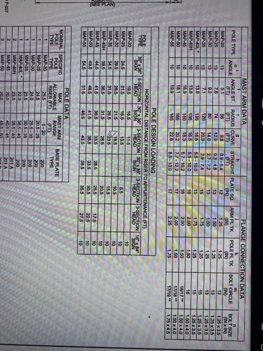
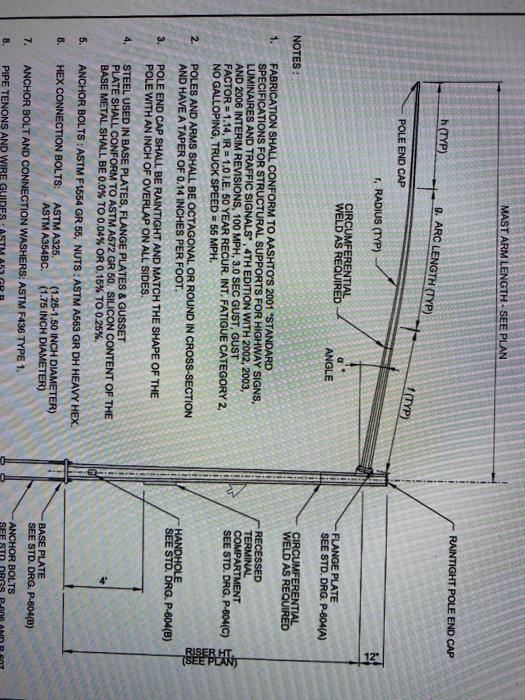
Analysis Assumptions Use the following parameters and simplifications/assumptions when analyzing the structure: Analyze the structure in 2D, as diagrammed in Dwg. No. P-601 Ignore the radius of the mast arm. Treat it as a straight member, inclined at angle a. The mast arm and post are fabricated from structural steel, with a unit weight of 490 pcf. Assume that the cross-sectional area (and therefore self-weight) of the mast arm and post linearly vary along the length/height of each member. The cross-sectional area at the end of each member is: Mast Arm End: 4.00 in? (at free end) Mast Arm Base: 10.0 in? (at connection to post) Post End: 12.0 in? (at connection to mast arm) Post Base: 24.0 in? (at bottom of post) Ignore the weight of bolt, caps, compartments, etc. and the voids in member-only consider the gross self-weight of the main structural tubing (mast arm and post). Ignore the 12" portion of the post that extends above the mast arm connection The bottom of the post is a fixed connection to the foundation 0 0 o Use the following geometry and loading parameters: Mast Arm Length: 30.0 ft (Horizontal) Post Riser Height: 24.0 ft (Vertical) Attached Signs/Signals: The following sign/signals are supported by the mast arm 0 Type Horiz. Distance From Post Centerline (ft) Weight (lbs) 30x36" Sign 29.5 100 5-Section Head 26.5 300 30"x36" Sign 21.5 100 3-Section Head 18.5 200 3-Section Head 10.5 200 Tasks to Complete A) Determinacy/Stability: Show that the structure is determinate and stable B) (Unfactored] Dead Load: Considering only the self-weight of the mast arm and the post a) Provide a loading diagram showing the dead load loading on the mast arm and post. Break-up the loading into components parallel and perpendicular to the members b) Develop equations for internal axial force (N), shear force (1), and bending moment (M) due to the dead load. Use units of feet and pounds. i) Mast Arm: Use a datum (i.e. x;=0ft) at the free end (.e. tip) of the arm ii) Post: Use a datum (i.e. x=0 ft) at the base (i.e. bottom) of the post c) Provide diagrams for internal axial force (N), shear force (V), and bending moment (M) due to the dead load. Clearly identify max/min values for each. Use units of feet and pounds. C) [Unfactored] Live Load: Considering only the weight of the signs and signals ("heads") a) Provide a loading diagram showing the live load loading on the mast arm and post. Break-up the loading into components parallel and perpendicular to the members b) DO NOT develop equations for N/V/M for live loads c) Provide diagrams for internal axial force (N), shear force (1), and bending moment (M) due to the live load. Clearly identify max/min values for each. Use units of feet and pounds. POLE TYPE MAST ARM DATA r 9 h ANGLE ANGLE ST. RADIUS CURVE STRAIGHT PLATE SQ (FT) (FD) (FT) (FT) (IN) 13 5.1 56 9.8 0.9-5.4 12 13 7.6 74 12.9 0.3-4.8 13 13 9.2 80 14.0 2.7-72 13 13 771 120 20.9 2.9-7.4 15 10 13.8 135 16.5 5.5 - 10.0 15 10 13.8 135 16.5 5.5 - 10.0 16 10 16.9 150 18,3 5.7 - 10.2 16 10 18.1 165 20.2 7.7 - 12.2 17 10 19.9 165 22.6 8.5. 13.0 17 MAP-20 MAP-25 MAP-30 MAP-35 MAP-40L MAP-40H MAP-45 MAP-50 MAP-55 FLANGE CONNECTION DATA m ARM PL TK POLE PL TK BOLT CIRCLE (IN) (IN) (IN) 1.25 1.25 12 1.50 1.25 13 1.50 13 1.75 1.25 15 1.75 1.25 15 2.00 1.50 16 2.00 1.50 16/17 2.00 1.50 17/18 2.25 1.75 17/19 1.25 n BOLT SIZE (IN X IN) 1.25 x 1.25 x 3.5 1.25 x 3.5 1.25 x 3,5 1.25 x 3.5 1.50 x 4.0 1.50 X 40 1.50 x 4.0 1.75 x 4.5 + . 1 POPE TYPE POLE DESIGN LOADING HORIZONTAL DISTANCE FROM RISER TO APPURTENANCE (FT) 3036' 5-SECTION 30" x 36" 3-SECTION 30" x 36" 3-SECTION 3-SECTION 169 x 34" SIGN HEAD SIGN HEAD SIGN HEAD HEAD SIGN 19.5 16.5 11.5 10 24.5 21.5 16.5 13.5 10 29.5 26.5 21.5 18.5 10.5 10 345 31.5 28.5 15,5 10 39.5 36.5 31.5 28.5 20.5 10 44.5 41.5 36.5 28.5 25.5 17.5 10 49.5 46.5 41.5 38.5 33.5 30.5 22.5 10 54.5 51.5 46.6 43.6 38.5 35.5 27.5 10 5.5 MAP-20 MAP-25 MAP-30 MAP-35 MAP-40H MAP-45 MAP-50 MAP-55 W23.5 TSEE PLAN) 33.5 BASE PLATE TYPE NOMINAL SPECIFIC POLE POLE TYPE TYPE 1 MAP-20 1 MAP-25 1 MAP-30 1 MAP-35 1 MAP-40L 2 MAP.40H 2 MAP-45 3 MAP-50 POLE DATA MAX MAST ARM ALLOWABLE RANGE RISER FO (FT) 25.5 5-20 24.5 20.5-25 24.0 25.5 - 30 23.5 30.5 - 35 22.0 35 5.40 23.5 35,5-40 20.0 40,5-46 20.0 45.5-50 200 200 200 200 200 201 A 201A ONN- P-807 MAST ARM LENGTH - SEE PLAN RAINTIGHT POLE END CAP h (TYP) 9. ARC LENGTH (TYP) T (TYP) POLE END CAP 1, RADIUS (TYP) CIRCUMFERENTIAL WELD AS REQUIRED ANGLE FLANGE PLATE SEE STD. DRG. P-804(A) NOTES: CIRCUMFERENTIAL WELD AS REQUIRED 1. RECESSED TERMINAL COMPARTMENT SEE STD. DRG. P-604(C) FABRICATION SHALL CONFORM TO AASHTO'S 2001 "STANDARD SPECIFICATIONS FOR STRUCTURAL SUPPORTS FOR HIGHWAY SIGNS, LUMINAIRES AND TRAFFIC SIGNALS, 4TH EDITION WITH 2002, 2003, AND 2006 INTERIM REVISIONS, 100 MPH, 3.0 SEC GUST, GUST FACTOR = 1.14, IR = 1.0 1.E. 50 YEAR RECUR. INT. FATIGUE CATEGORY 2, NO GALLOPING, TRUCK SPEED = 55 MPH. POLES AND ARMS SHALL BE OCTAGONAL OR ROUND IN CROSS-SECTION AND HAVE A TAPER OF 0.14 INCHES PER FOOT. POLE END CAP SHALL BE RAINTIGHT AND MATCH THE SHAPE OF THE POLE WITH AN INCH OF OVERLAP ON ALL SIDES. STEEL USED IN BASE PLATES, FLANGE PLATES & GUSSET PLATE SHALL CONFORM TO ASTM A572 GR 50. SILICON CONTENT OF THE BASE METAL SHALL BE 0.0% TO 0.04% OR 0.15% TO 0.25% RISER TSEE PLAN 2. HANDHOLE SEE STD. DRG. P-604(B) 3. 4. 5. ANCHOR BOLTS: ASTM F1554 GR 55, NUTS: ASTM A563 GR DH HEAVY HEX. 6. HEX CONNECTION BOLTS: ASTM A325 ASTM A364BC. (1.25-1.50 INCH DIAMETER) (1.75 INCH DIAMETER) 7. ANCHOR BOLT AND CONNECTION WASHERS: ASTM F436 TYPE 1. BASE PLATE SEE STD. DRG. P-604(B) ANCHOR BOLTS SEE 8. PIPE TENONS AND WIRE GUI Analysis Assumptions Use the following parameters and simplifications/assumptions when analyzing the structure: Analyze the structure in 2D, as diagrammed in Dwg. No. P-601 Ignore the radius of the mast arm. Treat it as a straight member, inclined at angle a. The mast arm and post are fabricated from structural steel, with a unit weight of 490 pcf. Assume that the cross-sectional area (and therefore self-weight) of the mast arm and post linearly vary along the length/height of each member. The cross-sectional area at the end of each member is: Mast Arm End: 4.00 in? (at free end) Mast Arm Base: 10.0 in? (at connection to post) Post End: 12.0 in? (at connection to mast arm) Post Base: 24.0 in? (at bottom of post) Ignore the weight of bolt, caps, compartments, etc. and the voids in member-only consider the gross self-weight of the main structural tubing (mast arm and post). Ignore the 12" portion of the post that extends above the mast arm connection The bottom of the post is a fixed connection to the foundation 0 0 o Use the following geometry and loading parameters: Mast Arm Length: 30.0 ft (Horizontal) Post Riser Height: 24.0 ft (Vertical) Attached Signs/Signals: The following sign/signals are supported by the mast arm 0 Type Horiz. Distance From Post Centerline (ft) Weight (lbs) 30x36" Sign 29.5 100 5-Section Head 26.5 300 30"x36" Sign 21.5 100 3-Section Head 18.5 200 3-Section Head 10.5 200 Tasks to Complete A) Determinacy/Stability: Show that the structure is determinate and stable B) (Unfactored] Dead Load: Considering only the self-weight of the mast arm and the post a) Provide a loading diagram showing the dead load loading on the mast arm and post. Break-up the loading into components parallel and perpendicular to the members b) Develop equations for internal axial force (N), shear force (1), and bending moment (M) due to the dead load. Use units of feet and pounds. i) Mast Arm: Use a datum (i.e. x;=0ft) at the free end (.e. tip) of the arm ii) Post: Use a datum (i.e. x=0 ft) at the base (i.e. bottom) of the post c) Provide diagrams for internal axial force (N), shear force (V), and bending moment (M) due to the dead load. Clearly identify max/min values for each. Use units of feet and pounds. C) [Unfactored] Live Load: Considering only the weight of the signs and signals ("heads") a) Provide a loading diagram showing the live load loading on the mast arm and post. Break-up the loading into components parallel and perpendicular to the members b) DO NOT develop equations for N/V/M for live loads c) Provide diagrams for internal axial force (N), shear force (1), and bending moment (M) due to the live load. Clearly identify max/min values for each. Use units of feet and pounds. POLE TYPE MAST ARM DATA r 9 h ANGLE ANGLE ST. RADIUS CURVE STRAIGHT PLATE SQ (FT) (FD) (FT) (FT) (IN) 13 5.1 56 9.8 0.9-5.4 12 13 7.6 74 12.9 0.3-4.8 13 13 9.2 80 14.0 2.7-72 13 13 771 120 20.9 2.9-7.4 15 10 13.8 135 16.5 5.5 - 10.0 15 10 13.8 135 16.5 5.5 - 10.0 16 10 16.9 150 18,3 5.7 - 10.2 16 10 18.1 165 20.2 7.7 - 12.2 17 10 19.9 165 22.6 8.5. 13.0 17 MAP-20 MAP-25 MAP-30 MAP-35 MAP-40L MAP-40H MAP-45 MAP-50 MAP-55 FLANGE CONNECTION DATA m ARM PL TK POLE PL TK BOLT CIRCLE (IN) (IN) (IN) 1.25 1.25 12 1.50 1.25 13 1.50 13 1.75 1.25 15 1.75 1.25 15 2.00 1.50 16 2.00 1.50 16/17 2.00 1.50 17/18 2.25 1.75 17/19 1.25 n BOLT SIZE (IN X IN) 1.25 x 1.25 x 3.5 1.25 x 3.5 1.25 x 3,5 1.25 x 3.5 1.50 x 4.0 1.50 X 40 1.50 x 4.0 1.75 x 4.5 + . 1 POPE TYPE POLE DESIGN LOADING HORIZONTAL DISTANCE FROM RISER TO APPURTENANCE (FT) 3036' 5-SECTION 30" x 36" 3-SECTION 30" x 36" 3-SECTION 3-SECTION 169 x 34" SIGN HEAD SIGN HEAD SIGN HEAD HEAD SIGN 19.5 16.5 11.5 10 24.5 21.5 16.5 13.5 10 29.5 26.5 21.5 18.5 10.5 10 345 31.5 28.5 15,5 10 39.5 36.5 31.5 28.5 20.5 10 44.5 41.5 36.5 28.5 25.5 17.5 10 49.5 46.5 41.5 38.5 33.5 30.5 22.5 10 54.5 51.5 46.6 43.6 38.5 35.5 27.5 10 5.5 MAP-20 MAP-25 MAP-30 MAP-35 MAP-40H MAP-45 MAP-50 MAP-55 W23.5 TSEE PLAN) 33.5 BASE PLATE TYPE NOMINAL SPECIFIC POLE POLE TYPE TYPE 1 MAP-20 1 MAP-25 1 MAP-30 1 MAP-35 1 MAP-40L 2 MAP.40H 2 MAP-45 3 MAP-50 POLE DATA MAX MAST ARM ALLOWABLE RANGE RISER FO (FT) 25.5 5-20 24.5 20.5-25 24.0 25.5 - 30 23.5 30.5 - 35 22.0 35 5.40 23.5 35,5-40 20.0 40,5-46 20.0 45.5-50 200 200 200 200 200 201 A 201A ONN- P-807 MAST ARM LENGTH - SEE PLAN RAINTIGHT POLE END CAP h (TYP) 9. ARC LENGTH (TYP) T (TYP) POLE END CAP 1, RADIUS (TYP) CIRCUMFERENTIAL WELD AS REQUIRED ANGLE FLANGE PLATE SEE STD. DRG. P-804(A) NOTES: CIRCUMFERENTIAL WELD AS REQUIRED 1. RECESSED TERMINAL COMPARTMENT SEE STD. DRG. P-604(C) FABRICATION SHALL CONFORM TO AASHTO'S 2001 "STANDARD SPECIFICATIONS FOR STRUCTURAL SUPPORTS FOR HIGHWAY SIGNS, LUMINAIRES AND TRAFFIC SIGNALS, 4TH EDITION WITH 2002, 2003, AND 2006 INTERIM REVISIONS, 100 MPH, 3.0 SEC GUST, GUST FACTOR = 1.14, IR = 1.0 1.E. 50 YEAR RECUR. INT. FATIGUE CATEGORY 2, NO GALLOPING, TRUCK SPEED = 55 MPH. POLES AND ARMS SHALL BE OCTAGONAL OR ROUND IN CROSS-SECTION AND HAVE A TAPER OF 0.14 INCHES PER FOOT. POLE END CAP SHALL BE RAINTIGHT AND MATCH THE SHAPE OF THE POLE WITH AN INCH OF OVERLAP ON ALL SIDES. STEEL USED IN BASE PLATES, FLANGE PLATES & GUSSET PLATE SHALL CONFORM TO ASTM A572 GR 50. SILICON CONTENT OF THE BASE METAL SHALL BE 0.0% TO 0.04% OR 0.15% TO 0.25% RISER TSEE PLAN 2. HANDHOLE SEE STD. DRG. P-604(B) 3. 4. 5. ANCHOR BOLTS: ASTM F1554 GR 55, NUTS: ASTM A563 GR DH HEAVY HEX. 6. HEX CONNECTION BOLTS: ASTM A325 ASTM A364BC. (1.25-1.50 INCH DIAMETER) (1.75 INCH DIAMETER) 7. ANCHOR BOLT AND CONNECTION WASHERS: ASTM F436 TYPE 1. BASE PLATE SEE STD. DRG. P-604(B) ANCHOR BOLTS SEE 8. PIPE TENONS AND WIRE GUI
