

Answered step by step
Verified Expert Solution
Question
1 Approved Answer
answer question 3 a-f 12V Figure 1-3 3. Answer the following questions based on Figure 1-3 (30-pt.). a). In the half-wave rectification circuit shown in
answer question 3 a-f
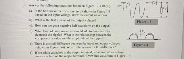
12V Figure 1-3 3. Answer the following questions based on Figure 1-3 (30-pt.). a). In the half-wave rectification circuit shown in Figure 1-3, based on the input voltage, draw the output waveform. b). What is the RMS value of the output voltage? c). How can we get a negative half waveform on the output? d). What kind of component we should add to this circuit to decrease the ripple? What is the relationship between the component's value and the amplitude of the ripple? e). There is a small difference between the input and output voltages (shown in Figure 1-4). What is the reason for this difference? f). If we add a capacitor in the output terminal, what kind of waveform we can obtain on the output terminal? Draw this waveform in Figure 1-4. Figure 1-4Step by Step Solution
There are 3 Steps involved in it
Step: 1

Get Instant Access to Expert-Tailored Solutions
See step-by-step solutions with expert insights and AI powered tools for academic success
Step: 2

Step: 3
Ace Your Homework with AI
Get the answers you need in no time with our AI-driven, step-by-step assistance
Get Started
Relational Database Design With Microcomputer Applications
Authors: Glenn A. Jackson
1st Edition
0137718411, 978-0137718412