Question
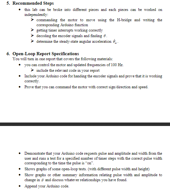
Arduino Help!!! I'm doing a code for a lab and its pretty much finished except for determining the steady state angular aceleration theta dot ss
Arduino Help!!! I'm doing a code for a lab and its pretty much finished except for determining the steady state angular aceleration theta dot ss its the last dot in section 5.
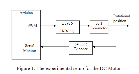
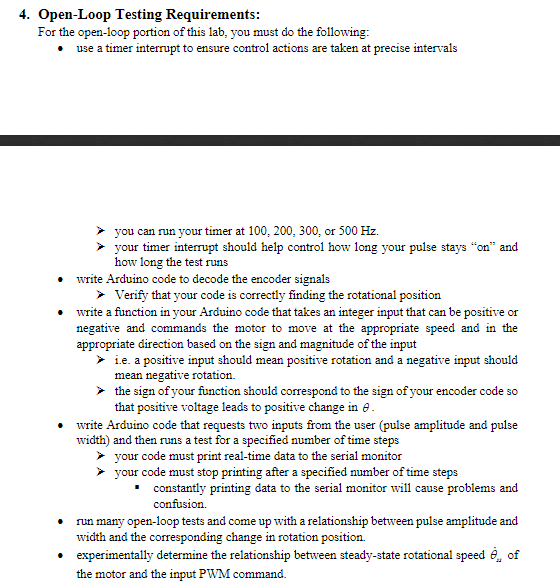
Code is posted below followed by relevant sections of lab so you can understand what has been done and why.
//#define encoderPinA 3 //#define encoderPinB 2 #include
// motor one int enA = 5; //analog pin (control speed of dc motor) int in1 = 7; //digital pin (control direction of dc motor) int in2 = 6; //digital pin (control direction of dc motor)
//Timer 0 #include
// Encoder pins // Verify that these are the same pins your encoder // A and B channels are connected to
Encoder knob(2,3);
//Timer 0 float dt_ms; float dt_sec; unsigned long t; unsigned long prevt; unsigned long t0; unsigned long tempt; float t_ms; float t_sec; int DC; //Chose a value between -255 to 255 (Duty Cycle) //Timer 1 int frequency; //Chose frequency (HZ)//sampling rate float timer_resolution=6.4e-5; //Timer Resolution (s) float target_time; float num; //counts float anglecounts; //Degrees float CPR=1920; //Counts per rev accounting for gear ratio float theta; //angle int pulse_width=10; float collection_time=14.0;
void setup() { Serial.begin(115200); Serial.println("Enter timer frequency (HZ)"); do { } while (Serial.available()
Serial.println("Enter Duty Cycle (-225 to 225)"); do { } while (Serial.available()
Serial.println("Pulse Width (How long motor will run--try 10 sec)"); do { } while (Serial.available()
Serial.println("Collection time (How long data will collect--MUST BE LARGER THAN PW)"); do { } while (Serial.available()
// Timer Resolution Calcualtion target_time= 1.0/frequency; num= (target_time/timer_resolution)-1;
// Initialize Timer 0
t0 = micros(); prevt = t0; t = t0; // Initialize Timer1 cli(); // disable global interrupts TCCR1A = 0; // set entire TCCR1A register to 0 TCCR1B = 0; // same for TCCR1B // set compare match register to desired timer count: OCR1A= num; //change this number to change the resolution of the timer //Serial.print(num);
// turn on CTC mode: TCCR1B |= (1
// Set CS10 and CS12 bits for 1024 prescaler: TCCR1B |= (1
// enable timer compare interrupt: TIMSK1 |= (1
// set all the motor control pins to outputs pinMode(enA, OUTPUT); pinMode(in1, OUTPUT); pinMode(in2, OUTPUT); }
void demoOne() { // this function will run the motors in both directions at the chosen PWM // turn on motor A if(DC>0 || DC==0) { digitalWrite(in1, HIGH); digitalWrite(in2, LOW); analogWrite(enA, DC ); } if(DC
void loop() { //Timer 0 prevt = t; t = micros(); dt_ms = (t-prevt)/1000; //step size of time in microseconds dt_sec = dt_ms/1000; //step size of time in seconds t_ms = (t-t0)/1000; //current i t_sec = t_ms/1000;
//Motor One demoOne(); if(t_sec>pulse_width) //Time the motor is running, after this the motor will shut off { digitalWrite(in1, LOW); digitalWrite(in2, LOW); } if(t_sec //Decode the encoder ISR(TIMER1_COMPA_vect) { anglecounts=knob.read(); theta=-anglecounts*(1.0/CPR)*(360.0); } 


Step by Step Solution
There are 3 Steps involved in it
Step: 1

Get Instant Access to Expert-Tailored Solutions
See step-by-step solutions with expert insights and AI powered tools for academic success
Step: 2

Step: 3

Ace Your Homework with AI
Get the answers you need in no time with our AI-driven, step-by-step assistance
Get Started


