Question
% assemble element stiffness matrix function K = assembly(K,e,ke) include_flags; for loop1 = 1:nen*ndof i = LM(loop1,e); for loop2 = 1:nen*ndof j = LM(loop2,e); K(i,j)
% assemble element stiffness matrix
function K = assembly(K,e,ke)
include_flags;
for loop1 = 1:nen*ndof
i = LM(loop1,e);
for loop2 = 1:nen*ndof
j = LM(loop2,e);
K(i,j) = K(i,j) + ke(loop1,loop2);
end
end
% file to include global variables
global nsd ndof nnp nel nen neq nd
global CArea E leng phi
global plot_truss plot_nod plot_stress
global LM IEN x y stress
% In class example based on problem 2.8-book
nsd = 2; % Number of space dimensions
ndof = 2; % Number of degrees-of-freedom per node
nnp = 8; % Number of nodal points
nel = 12; % Number of elements
nen = 2; % Number of nodes/ element
neq = ndof*nnp; % Number of equations
f = zeros(neq,1); % Initialize force vector
d = zeros(neq,1); % Initialize displacement matrix
K = zeros(neq); % Initialize stiffness matrix
%
flags = zeros(neq,1); % Initializeflags = zeros(neq,1); % Initialize flags
e_bc = zeros(neq,1); % Initializee-bc = zeros(neq,1); % Initialize flags
n_bc = zeros(neq,1); % Initializee-n-bc = zeros(neq,1); % Initialize flags
% Element properties
CArea = 2*[1 1 1 1 1 1 1 1 1 1 1 1]; % Elements area
E = 30e6*[1 1 1 1 1 1 1 1 1 1 1 1]; % Youngs Modulus
% % flags for forces and prescribed disp.
flags(15)=0;% horizontal force in node 2
flags(9:14)=3000; % Vertical Force
flags(7:8)=20; % pins ins nodes 3-5
n_bc(3)=30; %magnitude of force in dof 3
e_bc(15)=0; %magnitude of known displacements
% output plots
plot_truss = 'yes';
plot_nod = 'yes';
% mesh Generation
truss_mesh;
% function to plot the elements, global node numbers and print mesh parameters
function plotdisp(d)
include_flags;
% check if truss plot is requested
if strcmpi(plot_truss,'yes')==1;
for i = 1:nel
XX = [x(IEN(1,i)) x(IEN(2,i)) ];
YY = [y(IEN(1,i)) y(IEN(2,i)) ];
line(XX,YY);hold on;
mag=1e10; %magnification factor
%to visualize disp.
dx1=mag*d(IEN(1,i)*2-1);% dof in x of node 1
dx2=mag*d(IEN(2,i)*2-1);% dof in x of node 1
dy1=mag*d(IEN(1,i)*2);% dof in y of node 1
dy2=mag*d(IEN(2,i)*2);% dof in y of node 1
XX = [x(IEN(1,i))+dx1 x(IEN(2,i))+dx2];
YY = [y(IEN(1,i))+dy1 y(IEN(2,i))+dy2];
plot(XX,YY,'--r');hold on;
% check if node numbering is requested
if strcmpi(plot_nod,'yes')==1;
text(XX(1),YY(1),sprintf('%0.5g',IEN(1,i)));
text(XX(2),YY(2),sprintf('%0.5g',IEN(2,i)));
end
end
title('Truss Plot');
end
% print mesh parameters
fprintf(1,'\tTruss Params ');
fprintf(1,'No. of Elements %d ',nel);
fprintf(1,'No. of Nodes %d ',nnp);
fprintf(1,'No. of Equations %d ',neq);
% function to plot the elements, global node numbers and print mesh parameters
function plottruss
include_flags;
% check if truss plot is requested
if strcmpi(plot_truss,'yes')==1;
for i = 1:nel
XX = [x(IEN(1,i)) x(IEN(2,i)) ];
YY = [y(IEN(1,i)) y(IEN(2,i)) ];
line(XX,YY);hold on;
% check if node numbering is requested
if strcmpi(plot_nod,'yes')==1;
text(XX(1),YY(1),sprintf('%0.5g',IEN(1,i)));
text(XX(2),YY(2),sprintf('%0.5g',IEN(2,i)));
end
end
title('Truss Plot');
end
% print mesh parameters
fprintf(1,'\tTruss Params ');
fprintf(1,'No. of Elements %d ',nel);
fprintf(1,'No. of Nodes %d ',nnp);
fprintf(1,'No. of Equations %d ',neq);
% postprocessing function
function postprocessor(d)
include_flags;
% prints the element numbers and corresponding stresses
fprintf(1,'element\t\t\tstress ');
% compute stress vector
for e=1:nel
de = d(LM(:,e)); % displacement at the current element
const = E(e)/leng(e); % constant parameter within the element
if ndof == 1 % For 1-D truss element
stress(e) = const*([-1 1]*de);
end
if ndof == 2 % For 2-D truss element
p = phi(e)*pi/180; % Converts degrees to radians
c = cos(p); s = sin(p);
stress(e) = const*[-c -s c s]*de; % compute stresses
end
fprintf(1,'%d\t\t\t%f ',e,stress(e));
end
% preprocessing read input data and set up mesh information
function [K,f,d] = preprocessor
include_flags;
% input file to include all variables
input_file;
% generate LM array
for e = 1:nel
for j = 1:nen
for m = 1:ndof
ind = (j-1)*ndof + m;
LM(ind,e) = ndof*IEN(j,e) - ndof + m;
end
end
end
% partition and solve the system of equations
function [d,f_E] = solvedr(K,f,d)
include_flags;
% partition the matrix K, vectors f and d
K_E = K(1:nd,1:nd); % Extract K_E matrix
K_F = K(nd+1:neq,nd+1:neq); % Extract K_E matrix
K_EF = K(1:nd,nd+1:neq); % Extract K_EF matrix
f_F = f(nd+1:neq); % Extract f_F vector
d_E = d(1:nd); % Extract d_E vector
% solve for d_F
d_F =K_F\( f_F - K_EF'* d_E);
% reconstruct the global displacement d
d = [d_E
d_F];
% compute the reaction r
f_E = K_E*d_E+K_EF*d_F;
% write to the workspace
solution_vector_d = d
reactions_vector = f_E
% geometry and connectivity for example problem in Figure 2.8
function truss_mesh
include_flags;
% Nodal coordinates (origin placed at node 4)
x = [ 1 4 0 2 4 ]; % x coordinate
y = [ 1.73205078 2 0 0 0]; % y coordinate
% connectivity array
IEN = [3 4 1 4 5
1 1 2 2 2 ];
for i=1:nel
x1=x(IEN(1,i)); % x value of node 1
x2=x(IEN(2,i)); % x value of node 2
y1=y(IEN(1,i)); % y value of node 1
y2=y(IEN(2,i)); % y value of node 2
leng(i)=sqrt((x2-x1)^2+(y2-y1)^2);%length of el
phi(i)=acosd((x2-x1)/leng(i));
end
plottruss;

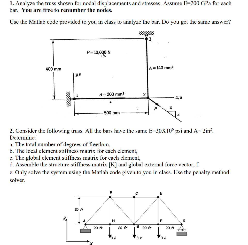
PLEASE SOLVE NUMBER 2 WITH THE CODE GIVEN BELOW> JUST HAVE TO FILL IN THE BLANKS WITH PROPPER FORCES
1. Analyze the truss shown for nodal displacements and stresses. Assume E-200 GPa for each bar. You are free to renumber the nodes. Use the Matlab code provided to you in class to analyze the bar. Do you get the same answer? P= 10,000 N 400 mm A-140 mm2 yyu A 200 mm2 2 x,u 4. 500 mm 3 2. Consider the following truss. All the bars have the same E-30X106 psi and A- 2in2 Determine: a. The total number of degrees of freedom b. The local element stiffness matrix for each element, c. The global element stiffness matrix for each element, d. Assemble the structure stiffness matrix [K] and global external force vector, f. e. Only solve the system using the Matlab code given to you in class. Use the penalty method solver. 20 ft 20 ft 20 ft G 20 ft 20 ft 3 k 3 k 3 k 1. Analyze the truss shown for nodal displacements and stresses. Assume E-200 GPa for each bar. You are free to renumber the nodes. Use the Matlab code provided to you in class to analyze the bar. Do you get the same answer? P= 10,000 N 400 mm A-140 mm2 yyu A 200 mm2 2 x,u 4. 500 mm 3 2. Consider the following truss. All the bars have the same E-30X106 psi and A- 2in2 Determine: a. The total number of degrees of freedom b. The local element stiffness matrix for each element, c. The global element stiffness matrix for each element, d. Assemble the structure stiffness matrix [K] and global external force vector, f. e. Only solve the system using the Matlab code given to you in class. Use the penalty method solver. 20 ft 20 ft 20 ft G 20 ft 20 ft 3 k 3 k 3 kStep by Step Solution
There are 3 Steps involved in it
Step: 1

Get Instant Access to Expert-Tailored Solutions
See step-by-step solutions with expert insights and AI powered tools for academic success
Step: 2

Step: 3

Ace Your Homework with AI
Get the answers you need in no time with our AI-driven, step-by-step assistance
Get Started


