Answered step by step
Verified Expert Solution
Link Copied!

Question

1 Approved Answer

Assignment Description: Design a one-bit half adder/subtractor circuit. In this circuit, the input variables a and b are two input bits of the operation and
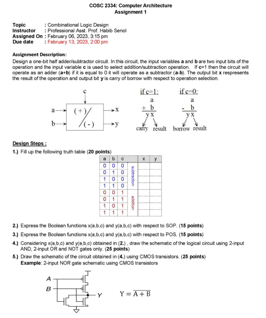
image text in transcribed

Assignment Description: Design a one-bit half adder/subtractor circuit. In this circuit, the input variables a and b are two input bits of the operation and the input variable c is used to select addition/subtraction operation. If c=1 then the circuit will operate as an adder (a+b) if it is equal to 0 it will operate as a subtractor (ab). The output bit x respresents the result of the operation and output bit y is carry of borrow with respect to operation selection. Design Steps: 1.) Fill up the following truth table (20 points) 2.) Express the Boolean functions x(a,b,c) and y(a,b,c) with respect to SOP. (15 points) 3.) Express the Boolean functions x(a,b,c) and y(a,b,c) with respect to POS. (15 points) 4.) Considering x(a,b,c) and y(a,b,c) obtained in (2.) , draw the schematic of the logical circuit using 2-input AND, 2-input OR and NOT gates only. (25 points) 5.) Draw the schematic of the circuit obtained in (4.) using CMOS transistors. (25 points) Example: 2-input NOR gate schematic using CMOS transistors

Step by Step Solution

There are 3 Steps involved in it

Step: 1

blur-text-image

Get Instant Access to Expert-Tailored Solutions

See step-by-step solutions with expert insights and AI powered tools for academic success

Step: 2

blur-text-image_2

Step: 3

blur-text-image_3

Ace Your Homework with AI

Get the answers you need in no time with our AI-driven, step-by-step assistance

Get Started

Recommended Textbook for

More Books

Students also viewed these Databases questions

Question

Understanding Group Leadership Culture and Group Leadership

Answered: 1 week ago