

Question
Assignment Instructions: 1) Consider the instruction slt, which has the format: slt $rd, $rs, $rt. a. The instruction sets $rd to 1 if and only
Assignment Instructions:
1) Consider the instruction slt, which has the format: slt $rd, $rs, $rt.
a. The instruction sets $rd to 1 if and only if $
i. Provide an informal RTL (register transfer language) describing the instruction semantics
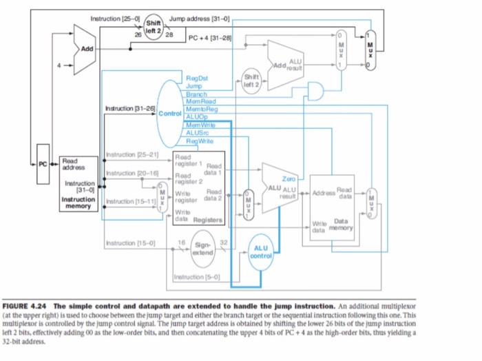
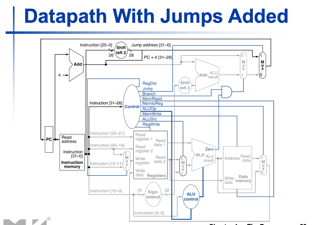
ii. Explain the way that the instruction is mapped into Figure 4.24 from the book by Patterson (below).
2) Consider the instruction slti, which has the format: slti $rt, $rs, constant.
a. The instruction sets $rt to 1 if and only if $
i. Provide an informal RTL (register transfer language) describing the instruction semantics
ii. Explain the way that the instruction is mapped into Figure 4.24 from the book by Patterson (below).
3) Consider the pseudo instruction b, which has the format: b label. The instruction performs an un-conditional branch relative to PC to the label specified in the instruction. Since this is a pseudo instruction, the assembler first convert it into a real instruction using beq.
i. Provide an informal RTL (register transfer language) describing the instruction semantics
ii. Explain the way that the instruction is mapped into Figure 4.24 from the book by Patterson (below).
4) Consider the instruction lw which has the format: lw $rt, offset($rs). The instruction loads the contents the memory address pointed to by $rs+offset into the register $rt.
i. Provide an informal RTL (register transfer language) describing the instruction semantics
ii. Explain the way that the instruction is mapped into Figure 4.24from the book by Patterson (below).
5) Consider the instruction jal, which has the format: jal label.
a. The instruction can be used to implement a function call.
i. Provide an informal RTL (register transfer language) describing the instruction semantics
ii. Explain the way that the instruction should be mapped into a modified version of Figure 4.24 from the book by Patterson (below). You can assume the availability of a control line jal and a micro instruction of the form: RF[31]
Step by Step Solution
There are 3 Steps involved in it
Step: 1

Get Instant Access to Expert-Tailored Solutions
See step-by-step solutions with expert insights and AI powered tools for academic success
Step: 2

Step: 3
Ace Your Homework with AI
Get the answers you need in no time with our AI-driven, step-by-step assistance
Get Started
Secrets Of Analytical Leaders Insights From Information Insiders
Authors: Wayne Eckerson
1st Edition
1935504347, 9781935504344