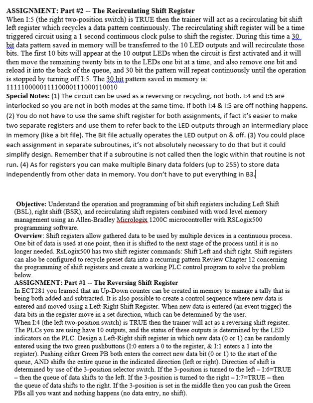
Question: ASSIGNMENT: Part #2-The Recirculating Shift Register When I5 (the right two-position switch) is TRUE then the trainer will act as a recirculating bit shift left


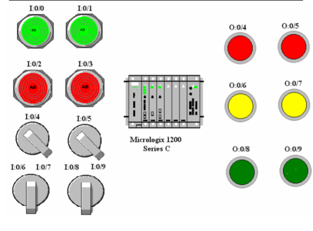
ASSIGNMENT: Part #2-The Recirculating Shift Register When I5 (the right two-position switch) is TRUE then the trainer will act as a recirculating bit shift left register which recycles a data pattern continuously. The recirculating shift register will be a time triggered circuit using a 1 second continuous clock pulse to shift the register. During this time a 30 bit data pattern saved in memory will be transferred to the 10 LED outputs and will recirculate those bits. The first 10 bits will appear at the 10 output LEDs when the circuit is first activated and it will then move the remaining twenty bits in to the LEDs one bit at a time, and also remove one bit and reload it into the back of the queue, and 30 bit the pattern will repeat continuously until the operation is stopped by turning off I:5. The 3Q bit pattern saved in memory is: Special Notes: (1) The circuit can be used as a reversing or recycling, not both. l:4 and 1:5 are interlocked so you are not in both modes at the same time. If both l:4 & 1:5 are off nothing happens. (2) You do not have to use the same shift register for both assignments, if fact it's easier to make two separate registers and use them to refer back to the LED outputs through an intermediary place in memory (like a bit file). The Bit file actually operates the LED output on & off. (3) You could place each assignment in separate subroutines, it's not absolutely necessary to do that but it could simplify design. Remember that if a subroutine is not called then the logic within that routine is not run. (4) As for registers you can make multiple Binary data folders (up to 255) to store data independently from other data in memory. You don't have to put everything in B3 Objective: Understand the operation and programming of bit shift registers including Left Shift (BSL), right shift (BSR), and recirculating shift registers combined with word level memory management using an Allen-Bradley Micrologix 1200C microcontroller with RSLogix500 programming software Overview: Shift registers allow gathered data to be used by multiple devices in a continuous process. One bit of data is used at one point, then it is shifted to the next stage of the process until it is no longer needed. RsLogix500 has two shift register commands: Shift Left and shift right. Shift registers can also be configured to recycle preset data into a recurring pattern Review Chapter 12 concerning the programming below ASSIGNMENT: Part #1-The Reversing Shift Register In ECT281 you learned that an Up-Down counter can be created in memory to manage a tally that is being both added and subtracted. It is also possible to create a control sequence where new data is entered and moved using a Left-Right Shift Register. When new data is entered (an event trigger) the data bits in the register move in a set direction, which can be d When I:4 (the left two-position switch) is TRUE then the trainer will act as a reversing shift register The PLCs you are using have 10 outputs, and the status of these outputs is determined by the LE indicators on the PLC. Design a Left-Right shift register in which new data (0 or1) can be randomly entered using the two green pushbuttons (I:0 enters a 0 to the register, & I1 enters a 1 into the register). Pushing either Green PB both enters the correct new data bit (0 or 1) to the start of the queue, AND shifts the entire queue in the indicated direction (left or right). Direction of shift is determined by use of the 3-position selector switch. If the 3-position is turned to the left I:6 TRUE - then the queue of data shifts to the left. If the 3-position is turned to the right I7-TRUE - then the queue of data shifts to the right. If the 3-position is set in the middle then you can push the Green PBs all you want and nothing happens (no data entry, no shift). of shift registers and create a working PLC control program to solve the problem the user Input Description Address Output Description Use the LEDs on the PLC O:0 to O:9 Address Input '0' to reversing 1:0 I:4 I:5 I:6 Input:1' to rev erung queue Input '1' to reversing queue Reversing Mode ON Recirculating Mode ON Shift Left Shift Right IO/O I:0/1 0:0/4 0:0/5 AS I0/2 L0/3 0:0/6 0:0/7 ABI AB ! I:0/4 I:OS Micrologix 1200 Series C 0:0/8 0:0/9 L06 L0/7 IoS L0r9 ASSIGNMENT: Part #2-The Recirculating Shift Register When I5 (the right two-position switch) is TRUE then the trainer will act as a recirculating bit shift left register which recycles a data pattern continuously. The recirculating shift register will be a time triggered circuit using a 1 second continuous clock pulse to shift the register. During this time a 30 bit data pattern saved in memory will be transferred to the 10 LED outputs and will recirculate those bits. The first 10 bits will appear at the 10 output LEDs when the circuit is first activated and it will then move the remaining twenty bits in to the LEDs one bit at a time, and also remove one bit and reload it into the back of the queue, and 30 bit the pattern will repeat continuously until the operation is stopped by turning off I:5. The 3Q bit pattern saved in memory is: Special Notes: (1) The circuit can be used as a reversing or recycling, not both. l:4 and 1:5 are interlocked so you are not in both modes at the same time. If both l:4 & 1:5 are off nothing happens. (2) You do not have to use the same shift register for both assignments, if fact it's easier to make two separate registers and use them to refer back to the LED outputs through an intermediary place in memory (like a bit file). The Bit file actually operates the LED output on & off. (3) You could place each assignment in separate subroutines, it's not absolutely necessary to do that but it could simplify design. Remember that if a subroutine is not called then the logic within that routine is not run. (4) As for registers you can make multiple Binary data folders (up to 255) to store data independently from other data in memory. You don't have to put everything in B3 Objective: Understand the operation and programming of bit shift registers including Left Shift (BSL), right shift (BSR), and recirculating shift registers combined with word level memory management using an Allen-Bradley Micrologix 1200C microcontroller with RSLogix500 programming software Overview: Shift registers allow gathered data to be used by multiple devices in a continuous process. One bit of data is used at one point, then it is shifted to the next stage of the process until it is no longer needed. RsLogix500 has two shift register commands: Shift Left and shift right. Shift registers can also be configured to recycle preset data into a recurring pattern Review Chapter 12 concerning the programming below ASSIGNMENT: Part #1-The Reversing Shift Register In ECT281 you learned that an Up-Down counter can be created in memory to manage a tally that is being both added and subtracted. It is also possible to create a control sequence where new data is entered and moved using a Left-Right Shift Register. When new data is entered (an event trigger) the data bits in the register move in a set direction, which can be d When I:4 (the left two-position switch) is TRUE then the trainer will act as a reversing shift register The PLCs you are using have 10 outputs, and the status of these outputs is determined by the LE indicators on the PLC. Design a Left-Right shift register in which new data (0 or1) can be randomly entered using the two green pushbuttons (I:0 enters a 0 to the register, & I1 enters a 1 into the register). Pushing either Green PB both enters the correct new data bit (0 or 1) to the start of the queue, AND shifts the entire queue in the indicated direction (left or right). Direction of shift is determined by use of the 3-position selector switch. If the 3-position is turned to the left I:6 TRUE - then the queue of data shifts to the left. If the 3-position is turned to the right I7-TRUE - then the queue of data shifts to the right. If the 3-position is set in the middle then you can push the Green PBs all you want and nothing happens (no data entry, no shift). of shift registers and create a working PLC control program to solve the problem the user Input Description Address Output Description Use the LEDs on the PLC O:0 to O:9 Address Input '0' to reversing 1:0 I:4 I:5 I:6 Input:1' to rev erung queue Input '1' to reversing queue Reversing Mode ON Recirculating Mode ON Shift Left Shift Right IO/O I:0/1 0:0/4 0:0/5 AS I0/2 L0/3 0:0/6 0:0/7 ABI AB ! I:0/4 I:OS Micrologix 1200 Series C 0:0/8 0:0/9 L06 L0/7 IoS L0r9
Step by Step Solution
There are 3 Steps involved in it

Get step-by-step solutions from verified subject matter experts


