Answered step by step
Verified Expert Solution
Question
1 Approved Answer
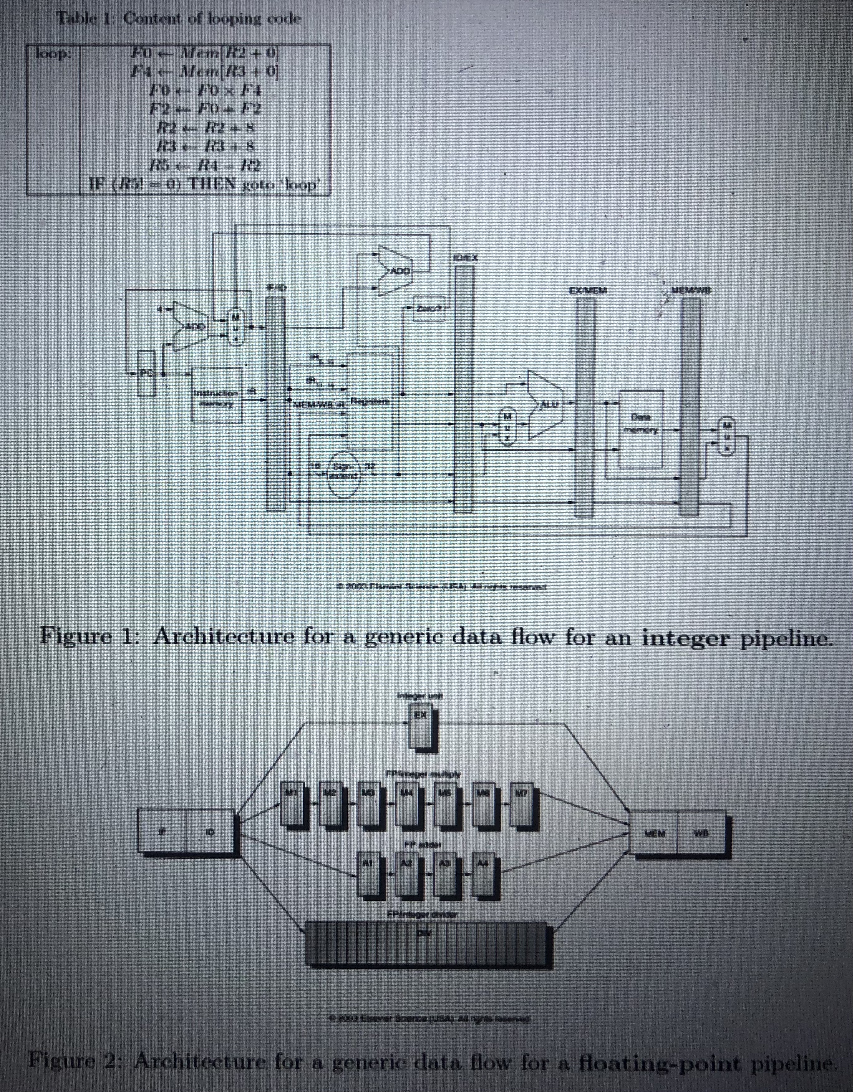
Assume the pipeline architecture of Figure 1 with floating point instructions following thepipeline of Figure 2 . Let all memory accesses be zero - wait
Assume the pipeline architecture of Figure with floating point instructions following thepipeline of Figure Let all memory accesses be zerowait state and assume that half cycleclocking is available for communicating results between general purpose registers during theWB and ID cycles. The units marked ADD will perform both addition and subtractionwhereas the ALU unit also supports logical operands.All questions refer to the code of Table in which the initial value for register R is R Note that Rx denotes an integer register and Fx a floating point register Compose a pipelinetiming diagram for the case of the code from Table and dataow of Figure illustrate the first two loops of execution There is no forwarding orbranch delay slot.a How many clock cycles are necessary to complete execution of all the code associated with a single loop?b On which clock cycle does the second loop commence?c How many clock cycles are executed before the last loop completes execution? Now assume that forwarding is available. Compose a pipelinetiming diagram for thisscenario and answer the following questions:a How many clock cycles are necessary to complete execution of all the code associated with a single loop?b On which clock cycle does the second loop commence?c How many clock cycles are executed before the last loop completes execution? Now assume that both forwarding and a branch delay slot is available. In order tomake use of the branch delay slot you may reorder the instructions, but cannot changeany operands or opcodes. Compose a pipelinetiming diagram for this scenario andanswer the following questions:a How many clock cycles are necessary to complete execution of all the code associated with a single loop?b On which clock cycle does the second loop commence?c How many clock cycles are executed before the last loop completes execution?Please make sure for the diagram that you take the instructions as columns and clock cycles as rows
Make sure you check figure as it states that FP int multiply: M MMM and FP adder A A A A also check the image for table and for fig
Please also make sure that for the diagrams: first column would be the instructions from table and the forst row would be clock cycles numbers and then fill the table with IF ID EX Mor A as should
Thank you

Step by Step Solution
There are 3 Steps involved in it
Step: 1

Get Instant Access to Expert-Tailored Solutions
See step-by-step solutions with expert insights and AI powered tools for academic success
Step: 2

Step: 3

Ace Your Homework with AI
Get the answers you need in no time with our AI-driven, step-by-step assistance
Get Started


