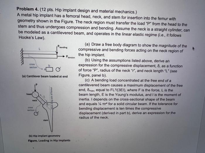
Problem 4. (12 pts. Hip implant design and material mechanics.) A metal hip implant has a femoral head, neck, and stem for insertion into

Problem 4. (12 pts. Hip implant design and material mechanics.) A metal hip implant has a femoral head, neck, and stem for insertion into the femur with geometry shown in the Figure. The neck region must transfer the load "P" from the head to the stem and thus undergoes compression and bending. Assume the neck is a straight cylinder, can be modeled as a cantilevered beam, and operates in the linear elastic regime (i.e., it follows Hooke's Law). cross section head (a) Cantilever beam loaded at end neck cross section O' bending ng axis offer tension (b) Hip implant geometry Figure. Loading in Hip Implants (a) Draw a free body diagram to show the magnitude of the compressive and bending forces acting on the neck region of the hip implant. (b) Using the assumptions listed above, derive an expression for the compressive displacement, , as a function of force "P", radius of the neck "r", and neck length "L" (see Figure, panel b). (c) A bending load concentrated at the free end of a cantilevered beam causes a maximum displacement of the free end, omax, equal to FL 3/(3EI), where F is the force, L is the beam length, E is the Young's modulus, and I is the moment of inertia. I depends on the cross-sectional shape of the beam and equals % TT for a solid circular beam. If the tolerance for bending displacement is ten times the compressive displacement (derived in part b), derive an expression for the radius of the neck.
Step by Step Solution
3.66 Rating (157 Votes )
There are 3 Steps involved in it
Step: 1
9 FBD Prono neck region rom R Vapsin...
See step-by-step solutions with expert insights and AI powered tools for academic success
Step: 2

Step: 3

Ace Your Homework with AI
Get the answers you need in no time with our AI-driven, step-by-step assistance
Get Started


