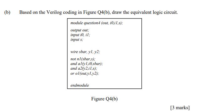
Question: (b) Based on the Verilog coding in Figure Q4(b), draw the equivalent logic circuit. module question4 (out, i0,il,s); output out; input i0, il; input
(b) Based on the Verilog coding in Figure Q4(b), draw the equivalent logic circuit. module question4 (out, i0,il,s); output out; input i0, il; input s; wire sbar, yl, y2; not n1 (sbar,s); and al(yl,i0,sbar): and a2(y2,i1,s); or ol (out.yl.y2); endmodule Figure Q4(b) [3 marks]
Step by Step Solution
There are 3 Steps involved in it

Get step-by-step solutions from verified subject matter experts
Document Format (2 attachments)
636050cd51121_231135.pdf
180 KBs PDF File
636050cd51121_231135.docx
120 KBs Word File


