

Question: ( b ) In the circuit shown in Figure 3 . 2 , the voltage source, ( widehat { v _ { i
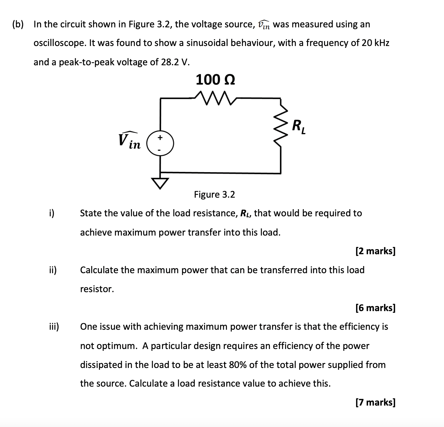
b In the circuit shown in Figure the voltage source, widehatvi n was measured using an oscilloscope. It was found to show a sinusoidal behaviour, with a frequency of kHz and a peaktopeak voltage of V
rigure angle
i State the value of the load resistance, boldsymbolRL that would be required to achieve maximum power transfer into this load.
marks
ii Calculate the maximum power that can be transferred into this load resistor.
marks
iii One issue with achieving maximum power transfer is that the efficiency is not optimum. A particular design requires an efficiency of the power dissipated in the load to be at least of the total power supplied from the source. Calculate a load resistance value to achieve this.
Step by Step Solution
There are 3 Steps involved in it
1 Expert Approved Answer
Step: 1 Unlock

Question Has Been Solved by an Expert!
Get step-by-step solutions from verified subject matter experts
Step: 2 Unlock
Step: 3 Unlock