Answered step by step
Verified Expert Solution
Question
1 Approved Answer
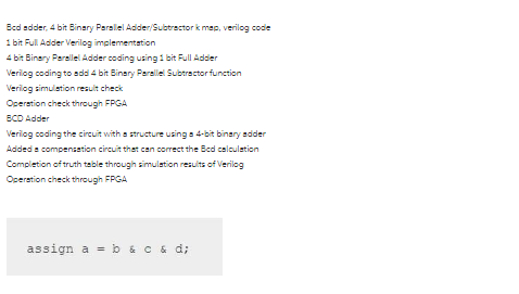
Bcd adder, 4 bit Binary Parallel Adder/Subtractor k map, verilog code 1 bit Full Adder Verilog implementation 4 bit Binary Parallel Adder coding using


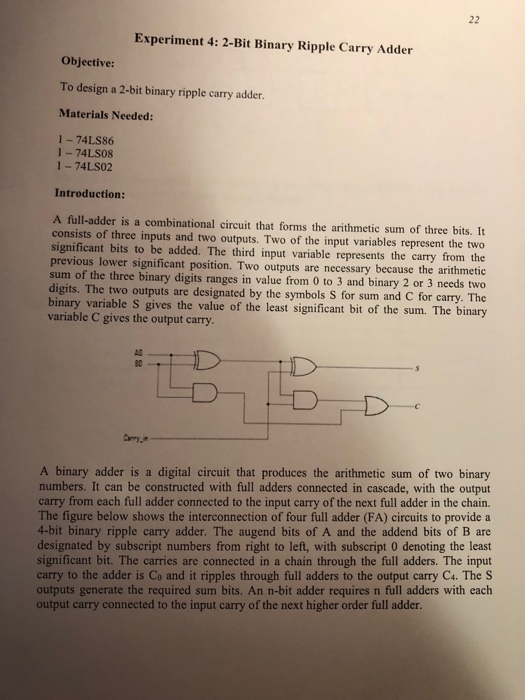
Bcd adder, 4 bit Binary Parallel Adder/Subtractor k map, verilog code 1 bit Full Adder Verilog implementation 4 bit Binary Parallel Adder coding using 1 bit Full Adder Verilog coding to add 4 bit Binary Parallel Subtractor function Verilog simulation result check Operation check through FPGA BCD Adder Verilog coding the circuit with a structure using a 4-bit binary adder Added a compensation circuit that can correct the Bcd calculation Completion of truth table through simulation results of Verilog Operation check through FPGA assign a b & c & d; Experiment 4: 2-Bit Binary Ripple Carry Adder 22 Objective: To design a 2-bit binary ripple carry adder. Materials Needed: 1-74LS86 1-74LS08 1-74LS02 Introduction: A full-adder is a combinational circuit that forms the arithmetic sum of three bits. It consists of three inputs and two outputs. Two of the input variables represent the two significant bits to be added. The third input variable represents the carry from the previous lower significant position. Two outputs are necessary because the arithmetic sum of the three binary digits ranges in value from 0 to 3 and binary 2 or 3 needs two digits. The two outputs are designated by the symbols S for sum and C for carry. The binary variable S gives the value of the least significant bit of the sum. The binary variable C gives the output carry. AC 80 Carry in A binary adder is a digital circuit that produces the arithmetic sum of two binary numbers. It can be constructed with full adders connected in cascade, with the output carry from each full adder connected to the input carry of the next full adder in the chain. The figure below shows the interconnection of four full adder (FA) circuits to provide a 4-bit binary ripple carry adder. The augend bits of A and the addend bits of B are designated by subscript numbers from right to left, with subscript 0 denoting the least significant bit. The carries are connected in a chain through the full adders. The input carry to the adder is Co and it ripples through full adders to the output carry C4. The S outputs generate the required sum bits. An n-bit adder requires n full adders with each output carry connected to the input carry of the next higher order full adder.
Step by Step Solution
There are 3 Steps involved in it
Step: 1

Get Instant Access to Expert-Tailored Solutions
See step-by-step solutions with expert insights and AI powered tools for academic success
Step: 2

Step: 3

Ace Your Homework with AI
Get the answers you need in no time with our AI-driven, step-by-step assistance
Get Started


