

Answered step by step
Verified Expert Solution
Question
1 Approved Answer
C E 4. A piston connecting rod and crank mechanism is illustrated in the figure. For this system, the crank is rotating at a constant
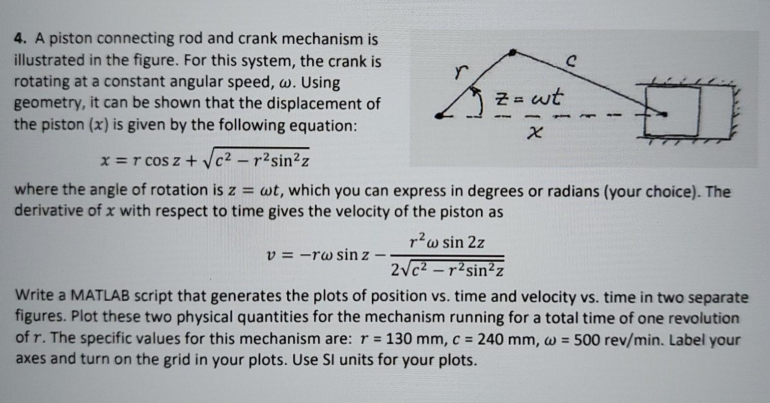
C E 4. A piston connecting rod and crank mechanism is illustrated in the figure. For this system, the crank is rotating at a constant angular speed, w. Using geometry, it can be shown that the displacement of Z= wt the piston (x) is given by the following equation: x x=r cos z + c2 - p2sin2z where the angle of rotation is z = wt, which you can express in degrees or radians (your choice). The derivative of x with respect to time gives the velocity of the piston as raw sin 2z v = -rw sin z 2vc2-rsinz Write a MATLAB script that generates the plots of position vs. time and velocity vs. time in two separate figures. Plot these two physical quantities for the mechanism running for a total time of one revolution of r. The specific values for this mechanism are: r = 130 mm, c = 240 mm, w = 500 rev/min. Label your axes and turn on the grid in your plots. Use SI units for your plots
Step by Step Solution
There are 3 Steps involved in it
Step: 1

Get Instant Access to Expert-Tailored Solutions
See step-by-step solutions with expert insights and AI powered tools for academic success
Step: 2

Step: 3
Ace Your Homework with AI
Get the answers you need in no time with our AI-driven, step-by-step assistance
Get Started
Expert Oracle9i Database Administration
Authors: Sam R. Alapati
1st Edition
1590590228, 978-1590590225