Question: C Programming MSP430F552x Demo - ADC12, Sample A10 Temp and Convert to oC and oF // // Description: A single sample is made on A10

C Programming
MSP430F552x Demo - ADC12, Sample A10 Temp and Convert to oC and oF // // Description: A single sample is made on A10 with reference to internal // 1.5V Vref. Software sets ADC12SC to start sample and conversion - ADC12SC // automatically cleared at EOC. ADC12 internal oscillator times sample // and conversion. In Mainloop MSP430 waits in LPM4 to save power until // ADC10 conversion complete, ADC12_ISR will force exit from any LPMx in // Mainloop on reti. // ACLK = n/a, MCLK = SMCLK = default DCO ~ 1.045MHz, ADC12CLK = ADC12OSC // // Uncalibrated temperature measured from device to devive will vary do to // slope and offset variance from device to device - please see datasheet. // // NOTE:1.REFMSTR bit in REFCTL0 regsiter is reset to allow the ADC12_A reference // control regsiters handle the reference setting. Upon resetting the REFMSTR // bit, all the settings in REFCTL are 'dont care' and the legacy ADC12 // control bits (ADC12REFON, ADC12REF2_5, ADC12TCOFF and ADC12REFOUT) control // the reference system. // 2. Use the TLV calibrated temperature to measure temperature // (the TLV CALIBRATED DATA IS STORED IN THE INFORMATION SEGMENT, SEE DEVICE DATASHEET) // // MSP430F552x // ----------------- // /|\| XIN|- // | | | // --|RST XOUT|- // | | // |A10 | // // F. Chen // Texas Instruments Inc. // Dec. 2012 // Built with IAR Embedded Workbench Version: 5.51.1 & Code Composer Studio V5.2.1 //******************************************************************************
#include
// Temperature Sensor Calibration = Reading at 30 degrees C is stored at addr 1A1Ah // See end of datasheet for TLV table memory mapping #define CALADC12_15V_30C *((unsigned int *)0x1A1A) // Temperature Sensor Calibration = Reading at 85 degrees C is stored at addr 1A1Ch //See device datasheet for TLV table memory mapping #define CALADC12_15V_85C *((unsigned int *)0x1A1C)
unsigned int in_temp;
int main(void) { volatile float temperatureDegC; volatile float temperatureDegF; volatile float degC_per_bit; volatile unsigned int bits30, bits85;
WDTCTL = WDTPW + WDTHOLD; // Stop WDT REFCTL0 &= ~REFMSTR; // Reset REFMSTR to hand over control of // internal reference voltages to // ADC12_A control registers ADC12CTL0 = ADC12SHT0_9 | ADC12REFON | ADC12ON; // Internal ref = 1.5V ADC12CTL1 = ADC12SHP; // Enable sample timer // Using ADC12MEM0 to store reading ADC12MCTL0 = ADC12SREF_1 + ADC12INCH_10; // ADC i/p ch A10 = temp sense // ACD12SREF_1 = internal ref = 1.5v
__delay_cycles(100); // delay to allow Ref to settle ADC12CTL0 |= ADC12ENC; // Enable conversion
// Use calibration data stored in info memory bits30 = CALADC12_15V_30C; bits85 = CALADC12_15V_85C; degC_per_bit = ((float)(85.0 - 30.0))/((float)(bits85-bits30));
while(1) { ADC12CTL0 &= ~ADC12SC; // clear the start bit ADC12CTL0 |= ADC12SC; // Sampling and conversion start // Single conversion (single channel)
// Poll busy bit waiting for conversion to complete while (ADC12CTL1 & ADC12BUSY) __no_operation(); in_temp = ADC12MEM0; // Read in results if conversion
// Temperature in Celsius. See the Device Descriptor Table section in the // System Resets, Interrupts, and Operating Modes, System Control Module // chapter in the device user's guide for background information on the // used formula. temperatureDegC = (float)((long)in_temp - CALADC12_15V_30C) * degC_per_bit +30.0;
// Temperature in Fahrenheit Tf = (9/5)*Tc + 32 temperatureDegF = temperatureDegC * 9.0/5.0 + 32.0; __no_operation(); // SET BREAKPOINT HERE } }
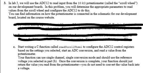
3. In lab 3, w will use the ADC12 to read input from the 10 k potentiometer (called the "scroll wheel"') on our development boards. In this problem, you will determine the appropriate parameters to read values from the scroll wheel and configure the ADC12 to do this You can find information on how the potentiometer is connected in the schematic for our development board, located on the course website. c. Start writing a C function called eadScroo configure the ADC12 control registers based on the settings you selected, start an ADC conversion, and read a value from the potentiometer Your function can use single channel, single conversion mode and should use the reference voltage you selected in part b). Once the conversion is complete, your function should just return the value you read from the potentiometer -you do not need to convert the value back into a voltage. 3. In lab 3, w will use the ADC12 to read input from the 10 k potentiometer (called the "scroll wheel"') on our development boards. In this problem, you will determine the appropriate parameters to read values from the scroll wheel and configure the ADC12 to do this You can find information on how the potentiometer is connected in the schematic for our development board, located on the course website. c. Start writing a C function called eadScroo configure the ADC12 control registers based on the settings you selected, start an ADC conversion, and read a value from the potentiometer Your function can use single channel, single conversion mode and should use the reference voltage you selected in part b). Once the conversion is complete, your function should just return the value you read from the potentiometer -you do not need to convert the value back into a voltage
Step by Step Solution
There are 3 Steps involved in it

Get step-by-step solutions from verified subject matter experts


