Question
C programming, Program Structure for Arduino: float ReadTemperature() Set CS LOW Read two bytes over SPI. Set CS HIGH convert temperature to Fahrenheit return temperature
C programming,
Program Structure for Arduino:
float ReadTemperature()
Set CS LOW
Read two bytes over SPI.
Set CS HIGH
convert temperature to Fahrenheit
return temperature
SetUp:
Set CS as an output
Configure SPI hardware
Configure Serial
Loop:
if 1 seconds has passed,
ReadTemperature();
Transmit temperature over Serial
end
--------------------------------------------------------------------------
more info


int TempBits = ( SPI.transfer16(0) >> 3 ) & 0x0fff; //Shift over 3, then mask off upper bits
float Temperature = 0.25 * ( float ) TempBits; // Convert to degrees Celsius
float Temperature = 1.8*Temperature + 32.0; // Convert to degrees Fahrenheit.

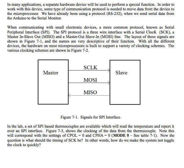
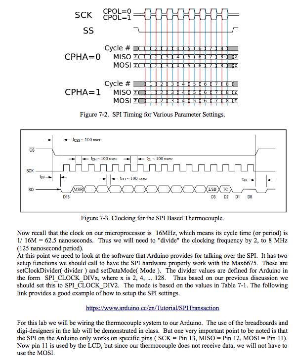
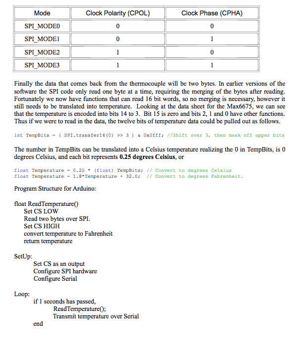
In many applications, a separate hardware device will be used to perform a special function. In order to work with this device, some type of communication protocol is needed to move data from the device to the microprocessor. We have already been using a protocol (RS-232), when we send serial data from the Arduino to the Serial Monitor. When communicating with small electronic devices, a more common protocol, known as Serial Peripheral Interface (SPI). The SPI protocol is a three wire interface with a Serial ClocK (SCK), a Master In-Slave Out (MISO) and a Master-Out Slave-In (MOSI) line. The layout of these signals are shown in Figure 7-1, and the names are very descriptive of their function. With all the different devices, the hardware on most microprocessors is built to support a variety of clocking schemes. The various clocking schemes are shown in Figure 7-2. SCLKslave MOSI MISO Master Figure 7-1. Signals for SPI Interface. In the lab, a set of SPI based thermocouples are available which will read the temperature and report it over an SPI interface. Figure 7-3, shows the clocking of the data from the thermocouple. Note this will correspond with the settings of CPOL = 0 and CPHA = 0 (MODE 0-See table 7-1). Now the question is what should the timing of SCK be? In other words, how do we make the system not toggle the clock to quickly? In many applications, a separate hardware device will be used to perform a special function. In order to work with this device, some type of communication protocol is needed to move data from the device to the microprocessor. We have already been using a protocol (RS-232), when we send serial data from the Arduino to the Serial Monitor. When communicating with small electronic devices, a more common protocol, known as Serial Peripheral Interface (SPI). The SPI protocol is a three wire interface with a Serial ClocK (SCK), a Master In-Slave Out (MISO) and a Master-Out Slave-In (MOSI) line. The layout of these signals are shown in Figure 7-1, and the names are very descriptive of their function. With all the different devices, the hardware on most microprocessors is built to support a variety of clocking schemes. The various clocking schemes are shown in Figure 7-2. SCLKslave MOSI MISO Master Figure 7-1. Signals for SPI Interface. In the lab, a set of SPI based thermocouples are available which will read the temperature and report it over an SPI interface. Figure 7-3, shows the clocking of the data from the thermocouple. Note this will correspond with the settings of CPOL = 0 and CPHA = 0 (MODE 0-See table 7-1). Now the question is what should the timing of SCK be? In other words, how do we make the system not toggle the clock to quickly
Step by Step Solution
There are 3 Steps involved in it
Step: 1

Get Instant Access to Expert-Tailored Solutions
See step-by-step solutions with expert insights and AI powered tools for academic success
Step: 2

Step: 3

Ace Your Homework with AI
Get the answers you need in no time with our AI-driven, step-by-step assistance
Get Started


