Answered step by step
Verified Expert Solution
Link Copied!
Question
1 Approved Answer

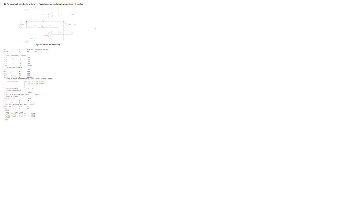
C2. For the circuit with Op-Amp shown in Figure 1, answer the following questions. (40 marks) Figure 1. Circuit with Op-Amp VS1 1 0 SIN(0V

C2. For the circuit with Op-Amp shown in Figure 1, answer the following questions. (40 marks) Figure 1.

Circuit with Op-Amp

VS1 1 0 SIN(0V 10VPEAK 1KHZ) VREF 10 0 DC 0V * * NON-INVERTING OUTPUT R11 0 12 10K R12 12 14 10K R13 1 13 10K R14 13 10 10K XOP1 13 12 14 OPAMP1 * INVERTING OUTPUT R21 1 22 10K R22 22 24 10K R23 0 23 10K R24 23 10 10K XOP2 23 22 24 OPAMP1 * SINGLE-POLE OPERATIONAL AMPLIFIER MACRO-MODEL * connections: non-inverting input * | inverting input * | | output * | | | .SUBCKT OPAMP1 1 2 6 * INPUT IMPEDANCE RIN 1 2 10MEG * DC GAIN (100K) AND POLE 1 (100HZ) * GBWP = 10MHZ EGAIN 3 0 1 2 100K RP1 3 4 1K CP1 4 0 1.5915UF * OUTPUT BUFFER AND RESISTANCE EBUFFER 5 0 4 0 1 ROUT 5 6 10 .ENDS .TRAN 0.01MS 2MS .PLOT TRAN V(1) V(14) V(24) .PRINT TRAN V(1) V(14) V(24) .PROBE .END Assessment Part C:

a) Describe the function of the circuit. (4 marks) (Insert your answer here)

b) Derive an expression to calculate the gain of the circuit (Vo/Vin). (4 marks) (Insert your answer here)

c) Use the expression you found in b) to calculate the maximum and minimum voltages at Vo. (Vin is a 1KHz, 10V sinewave) (4 marks) (Insert your answer here)

d) Simulate the circuit using the given data and take a screen shot of the out puts and input. (20) (Insert a screenshot of your diagram here)

e) If the Op-Amp is powered with 12V, list 4 changes you could do to the diagram to saturate the Op-Amp. Simulate one of the cases and take a screen shot. (8 Marks) (Insert a screenshot of your diagram here)image text in transcribedimage text in transcribedimage text in transcribed

V S110SINOV10V PEAK1KHZ)V REF100DCOV**NON-INVERTINGOUTPUTR1101210K R12121410K R1311310K R14131010K XOP11312140PAM P1* INVERTINGOUT PUTR2112210K R22222410K R2302310K R24231010K XOP22322240 PAM P1* SINGLE-POLEOPERATION ALAM PLIFIERM AC RO-MODEL* connections: non-invertinginputx|invertinginput*||output* |||.SUBCKTOPAM P1126* INPUTIMPEDANCERIN 1210 MEG*DCGAIN(100K)ANDPOLE1(100 HZ)* GBWP = 10M HZEGAIN3012100K RP1341KCP1401.5915U F*OUTPUT BUFFERANDRESISTANCEE BUFFER50401 ROUT5610.ENDS.TRAN0.01M S2MS.PLOTTRANV(1)V (14) V(24).PRINTTRANV(1) V(14)V(24).PROBE.END Figure 1. Circuit with Op Amp a) Describe the function of the circuit. (4 marks) (Insert your answer here) b) Derive expression to calculate the gain of the circuit (Vo/Vin). (4 marks) (Insert your answer here) C) Use the expression you found in b) to calculate the maximum and minimum voltages at Vo. (Vin is a 1KHz, 10V Sinewave) (4 marks) (Insert your answer here) d) Simulate the circuit using the given data and take a screen shot of the outputs and input. (20) (Insert a screenshot your diagram here) e) If the Op-Amp is powered with +12V, list 4 changes you could do to the diagram to saturate the Op-Amp. Simulate one of the cases and take a screen shot. (8 Marks) (Insert a screenshot of your diagram here) V S110SINOV10V PEAK1KHZ)V REF100DCOV**NON-INVERTINGOUTPUTR1101210K R12121410K R1311310K R14131010K XOP11312140PAM P1* INVERTINGOUT PUTR2112210K R22222410K R2302310K R24231010K XOP22322240 PAM P1* SINGLE-POLEOPERATION ALAM PLIFIERM AC RO-MODEL* connections: non-invertinginputx|invertinginput*||output* |||.SUBCKTOPAM P1126* INPUTIMPEDANCERIN 1210 MEG*DCGAIN(100K)ANDPOLE1(100 HZ)* GBWP = 10M HZEGAIN3012100K RP1341KCP1401.5915U F*OUTPUT BUFFERANDRESISTANCEE BUFFER50401 ROUT5610.ENDS.TRAN0.01M S2MS.PLOTTRANV(1)V (14) V(24).PRINTTRANV(1) V(14)V(24).PROBE.END Figure 1. Circuit with Op Amp a) Describe the function of the circuit. (4 marks) (Insert your answer here) b) Derive expression to calculate the gain of the circuit (Vo/Vin). (4 marks) (Insert your answer here) C) Use the expression you found in b) to calculate the maximum and minimum voltages at Vo. (Vin is a 1KHz, 10V Sinewave) (4 marks) (Insert your answer here) d) Simulate the circuit using the given data and take a screen shot of the outputs and input. (20) (Insert a screenshot your diagram here) e) If the Op-Amp is powered with +12V, list 4 changes you could do to the diagram to saturate the Op-Amp. Simulate one of the cases and take a screen shot. (8 Marks) (Insert a screenshot of your diagram here)
Step by Step Solution

There are 3 Steps involved in it

Step: 1

blur-text-image
Get Instant Access to Expert-Tailored Solutions

See step-by-step solutions with expert insights and AI powered tools for academic success

Step: 2

blur-text-image_2

Step: 3

blur-text-image_3

Ace Your Homework with AI

Get the answers you need in no time with our AI-driven, step-by-step assistance

Get Started

Recommended Textbook for

Database And Expert Systems Applications 33rd International Conference Dexa 2022 Vienna Austria August 22 24 2022 Proceedings Part 1 Lncs 13426

Authors: Christine Strauss ,Alfredo Cuzzocrea ,Gabriele Kotsis ,A Min Tjoa ,Ismail Khalil

1st Edition

3031124227, 978-3031124228

More Books

Students explore these related Databases questions