Answered step by step
Verified Expert Solution
Question
1 Approved Answer
Can anyone explain to solve this question? Equation (1): A laboratory-scale, ablatively-cooled ethylene/oxygen bi-propellant rocket engine is designed to produce 5lbf of thrust with a
Can anyone explain to solve this question?


Equation (1):

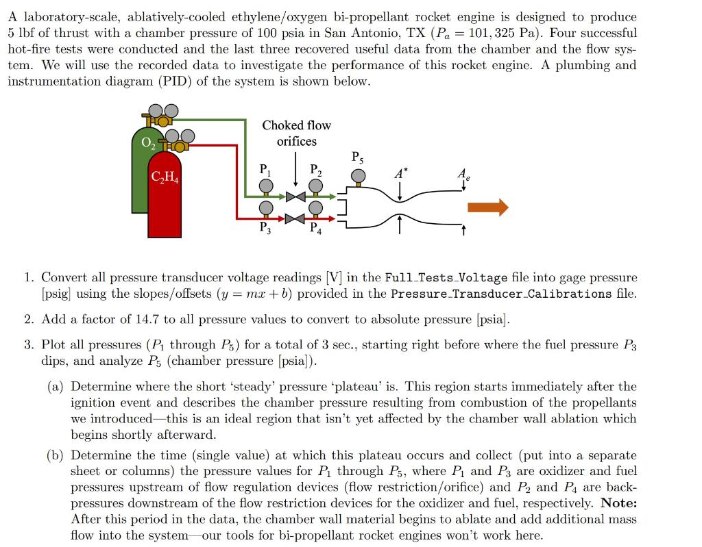
A laboratory-scale, ablatively-cooled ethylene/oxygen bi-propellant rocket engine is designed to produce 5lbf of thrust with a chamber pressure of 100 psia in San Antonio, TX (Pa=101,325Pa). Four successful hot-fire tests were conducted and the last three recovered useful data from the chamber and the flow system. We will use the recorded data to investigate the performance of this rocket engine. A plumbing and instrumentation diagram (PID) of the system is shown below. 1. Convert all pressure transducer voltage readings [V] in the Full_Tests_Voltage file into gage pressure [psig] using the slopes/offsets (y=mx+b) provided in the Pressure_Transducer_Calibrations file. 2. Add a factor of 14.7 to all pressure values to convert to absolute pressure [psia]. 3. Plot all pressures (P1 through P5) for a total of 3 sec., starting right before where the fuel pressure P3 dips, and analyze P5 (chamber pressure [psia]). (a) Determine where the short 'steady' pressure 'plateau' is. This region starts immediately after the ignition event and describes the chamber pressure resulting from combustion of the propellants we introduced - this is an ideal region that isn't yet affected by the chamber wall ablation which begins shortly afterward. (b) Determine the time (single value) at which this plateau occurs and collect (put into a separate sheet or columns) the pressure values for P1 through P5, where P1 and P3 are oxidizer and fuel pressures upstream of flow regulation devices (flow restriction/orifice) and P2 and P4 are backpressures downstream of the flow restriction devices for the oxidizer and fuel, respectively. Note: After this period in the data, the chamber wall material begins to ablate and add additional mass flow into the system - our tools for bi-propellant rocket engines won't work here. Confirm that the pressure ratios across the flow restriction devices for both the oxidizer (P2/P1) and fuel (P4/P3) at this timestep for these collected values are less than 0.8 (a ratio specific to this engine) to enable use of the choked flow orifice equation (Eqn. 1). m=CDA1P1(+12)1+1
Step by Step Solution
There are 3 Steps involved in it
Step: 1

Get Instant Access to Expert-Tailored Solutions
See step-by-step solutions with expert insights and AI powered tools for academic success
Step: 2

Step: 3

Ace Your Homework with AI
Get the answers you need in no time with our AI-driven, step-by-step assistance
Get Started


