can you please do scenario 6.a
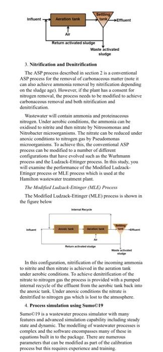
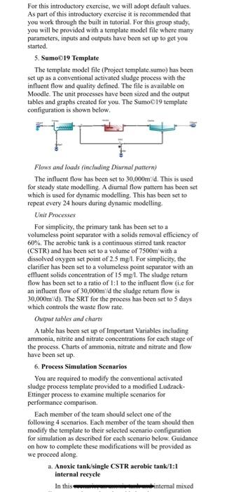
1. Introduction In this wastewater project you will undertake process simulation using Samob19 of the activated sludge process and examine options to achieve Nitrification and Denitrification of the wastewater flow. You will be assigned to groups of four to undertake this study. You will be required to undertake some research of the literature on the evolution of the activated sludge process for biological nitrogen and phosphorus removal as part of your project and include a short literature review as part of the report. The report will be a group report with each member of the team contributing to the wbole. Each group member will undertake the simulation of one scenario detailed later in this brief and the group will need to work together to examine and discuss the results and performance of the plant for inclusion in the report. This brief will cover the following sections: - A brief recap of the activated sludge process - Nitrification and denitrification of wastewater - Process simulation using SumoO19 - Sumoo 19 template file provided as a starting point - The process simulation scenarios to be undertaken - The group report structure and length - Submission details and group contribution form 2. The Activated Sludge Process The activated sludge process was introduced previously in ENGEV341. The process dates back to early tests conducted by Arden and Lockett in 1911 at the Davyhulme wastewater treatment plant in Manchester, England. Since then, the process has evolved and is capable of achieving biological nitrogen and phosphorus removal through a number of modifications. The conventional activated sludge process or ASP comprises two units. A biological reactor and a clarifier. The settled wastewater from the primary treatment stage is introduced into the biological reactor along with recyeled activated sludge or RAS from the clarifier. Microorganisms in the return shudge are mixed thoroughly with the organic compounds present in the incoming wastewater. The microorganisms grow in the biological reactor under acrobic conditions. Air is introduced into the aerobic reactor to maintain a dissolved oxygen set point for the process and mixing. As the microorganisms grow and are mixed by the agitation of air, the individual organisms flocculate to form an active mass of microbes called activated sludge. The mixed liquor of activated sludge passes to the elarifier where the solids are separated and recycled to the inlet to the biological reactor. The clarified water discharges over weirs from the clarifier and passes to the next stage of treatment or is discharged to the receiving water. Since the biomass is continuously growing and recucled into the process, an - The process simulation scenarios to be undertaken - The group report structure and length - Submission details and group contribution form 2. The Activated Sludge Process The activated sludge process was introduced previously in ENGEV341. The process dates beck to early tests conducted by Arden and Lockett in 1911 at the Davyhulme wastewater treatment plant in Manchester, England. Since then, the process has evolved and is capable of achieving biological nitrogen and phosphorus removal through a number of modifications. The conventional activated sludge process or ASP comprises two units. A biological reactor and a clarifier. The settled wastewater from the primary treatment stage is introduced into the biological reactor along with recyeled activated sludge or RAS from the clarifier. Microorganisms in the return sludge are mixed thonoughly with the organic compounds present in the incoming wastewater. The microorganisms grow in the biological reactor under acrobic conditions. Air is introduced into the acrobic reactor to maintain a dissolved oxygen set point for the process and mixing. As the microorganisms grow and are mixed by the agitation of air, the individual organisms flocculate to form an active mass of microbes called activated sludge. The mixed liquor of activated sludge passes to the clarifier where the solids are separated and recycled to the inlet to the biological reactor. The clarified water discharges over weirs from the clarifier and passes to the next stage of treatment or is discharged to the receiving water. Since the biomass is continuously growing and recycled into the process, an amount must be wasted each day to maintain steady state conditions. This is the waste activated sludge or WAS. Aeration tank stage comprises: Long, rectangular basin. - Acrated for 4-8 hours. Keeps microbes in suspension Consumes the organic matter in the incoming flow Clarifier stage: - Separates the activated sludge from the effluent most of which is returned into the aeration tank as RAS - Waste activated sludge is removed to maintain steady state conditions A portion of the sludge is wasted (WAS) every day to maintain the proper amount of microbes to efficiently oxidise the biodegradable organics. The average retention time of the sludge in the system is known as the sludge age and can range from less than 3 days to greater than 21 days depending on the process chosen. The ASP is shown in the figure below. 3. Nitrification and Denitrification The ASP process described in section 2 is a conventional ASP process for the removal of carbonaceous matter (note it can also achieve ammonia renoval by nitrification depending on the sludge age). However, if the plant has a consent for nitrogen removal, the process needs to be modified to achieve carbonaceous removal and both nitrification and denitrification. Wastewater will contain ammonia and proteinaceous nitrogen. Under acrobic conditions, the ammonia can be oxidised to nitrite and then nitrate by Nitrosomonas and Nitrobacter microorganisms. The nitrate can be reduced under anoxic conditions to nitrogen gas by Pseudomonas microorganisms. To achieve this, the conventional ASP process can be modified to a number of different configurations that have evolved such as the Wurhmann process and the Ludzack-Ettinger process. In this study, you will examine the performance of the Modified LadrackEttinger process or MLE process which is used at the Hamilton wastewater treatment plant. The Modified Ludack-Etringer (MLE) Process The Modified Ludrack-Ettinger (MLE) process is shown in the figure below In this conliguration, nitrification of the incoming ammonia to nitrite and then nitrate is achieved in the aeration tank under aerobic conditions. To achieve denitrification of the nitrate to nitrogen gas the process is provided with a pumped internal recycle of the effluent from the acrobic tank back into the anoxjc tank. Under anoxic conditions the nitrate is denitrified to nitrogen gas which is lost to the atmosphere. 4. Process simulation using Sumoo19 SumoC19 is a wastewater process simulator with many features and advanced simulation capability inchuding steady state and dynamic. The modelling of wastewater proceses is complex and the software encompasses many of these in equations built in to the package. There are numerous parameters that can be modified as part of the calibration process but this requires experience and training. For this introductory exercise, we will adopt default values. As part of this introductory exercise it is recommended that you work through the built in tutorial. For this group study. you will be provided with a template model file where many parameters, inputs and outputs have been set up to get you started. 5. Sum0019 Template The template model file (Project template.sunso) has been set up as a conventional activated sludge process with the influent flow and quality defined. The file is available on Moodle. The unit processes have been sized and the output tables and graphs created for you. The Sumo 19 template configuration is shown below. Flews and loads finchiding Diurnal pattern) The influent flow has been set to 30,000m//. This is used for steady state modelling A diurnal flow pattern has been set which is used for dyzamic modelling. This has been set to repeat every 24 hours during dynamic modelling. Unit Processes For simplicity, the primary tank has been set to a volumeless point separator with a solids removal efficiency of 60%. The aerobic tank is a continuous stirred tank reactor (CSTR) and has been set to a volume of 7500m ' with a dissolved oxygen set point of 2.5mg 1. For simplicity, the clarifier has been set to a volumeless point separator with an effluent solids concentration of 15mg/. The sludse return flow has been set to a ratio of 1:1 to the influent flow (i.e for an influent flow of 30,000n/1/ the sludge return flow is 30,000m/d ). The SRT for the process has been set to 5 days which controls the waste flow rate. Output tables and charts A table has been set up of Important Variables including ammonia, nitrite and nitrate concentrations for each stage of the process. Charts of ammonia, nitrate and nitrate and flow have been set up. 6. Process Simulation Scenarios You are required to modify the conventional activated sludge process template provided to a modified LudzackEttinger process to examine multiple scenarios for performance comparison. Each member of the team should seleet one of the following 4 scenarios. Each member of the team should then modify the template to their selected seenario configuration for simulation as described for each scenario below. Guidance on bow to complete these modifications will be provided as we proceed along. a. Anoxic tank/single CSTR aerobic tank/1:1 internal reeycle In this internal mixed for steady state modelling. A diurnal flow pattem has been set which is used for dynamic modelling. This has been set to repeat every 24 hours during dynamic modelling. Unit Pracerses For simplicity, the primary tank has been set to a volumeless point separator with a solids removal efficiency of 602. The acrobic tank is a continuous stirred tank reactor (CSTR) and has been set to a volume of 7500m ' with a dissolved oxygen set point of 2.5mg/. For simplicity, the clarifier has been set to a volumeless point separator with an effluent solids concentration of 15mg. The sludge return flow has been set to a ratio of 1:1 to the influent flow (t.e for an influent flow of 30,000m '/d the sludge return flow is 30,000m/d ). The SRT for the process has been set to 5 days which controls the waste flow rate. Ourput tables and charts A table has been set up of Important Variables including ammonia, nitrite and nitrate concentrations for each stage of the process. Charts of ammonia, nitrate and nitrate and flow have been set up. 6. Process Simulation Scenarios You are required to modify the conventional activated sludge process template provided to a modified LudzackEttinger process to examine multiple scenarios for performance comparison. Each member of the team should select one of the following 4 scenarios. Each member of the team should then modify the template to their selected scenario configuration for simulation as described for cach scenario below. Gudance on how to complete these modifications will be provided as we proceed along. a. Anoxic tank/single CSTR aerobic tank/1:1 internal recycle In this scenario, an anoxic tank and internal mixed liquor recycle needs to be added to the process configuration to convert the conventional activated sludge process to the MLE process for nitrification and denitrification. The anoxic tank volume should be inserted before the acrobic tank as a CSTR and set to a volume of 3000m '. The air flow needs to be set to zero for anoxic conditions. To provide the internal mixed liquor recycle, a pumped flow splitter will need to be inserted after the acrobic tank and a flow combiner inserted before the anoxic tank. A pipe connecting the pumped flow splitter to the flow combiner will need to be added and the internal recyele to influent flow ratio set to 1:1. The anoxic tank will need to be added to the Total SRT ealculation. The Dissolved Oxygen will need to be set to calculated for the anoxic tank. b. Anoxic tankisingle CSTR aerobic tank/3:1 internal recycle In this scenario, an anoxic tank and internal mixed liquor recycle needs to be added to the process configuration to convert the conventional activated


