Answered step by step
Verified Expert Solution
Question
1 Approved Answer
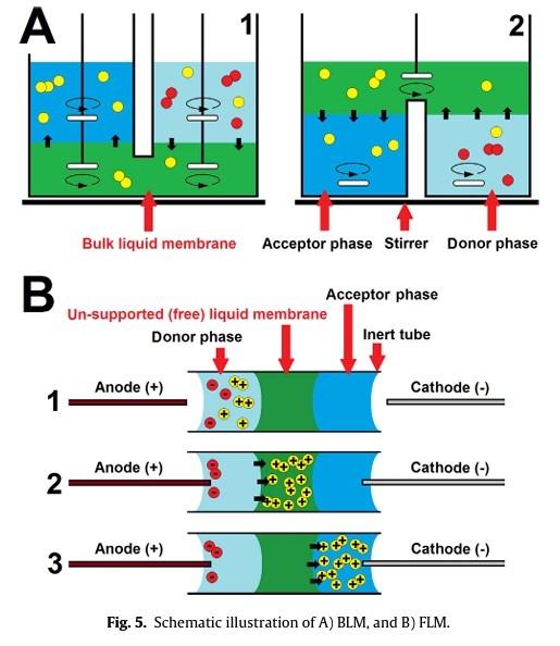
Can you please give brief informations about all of these figures one by one on the subject of membrane processes in pharmaceutical industry? Fig. 1.
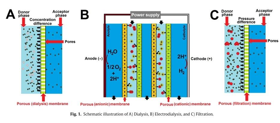
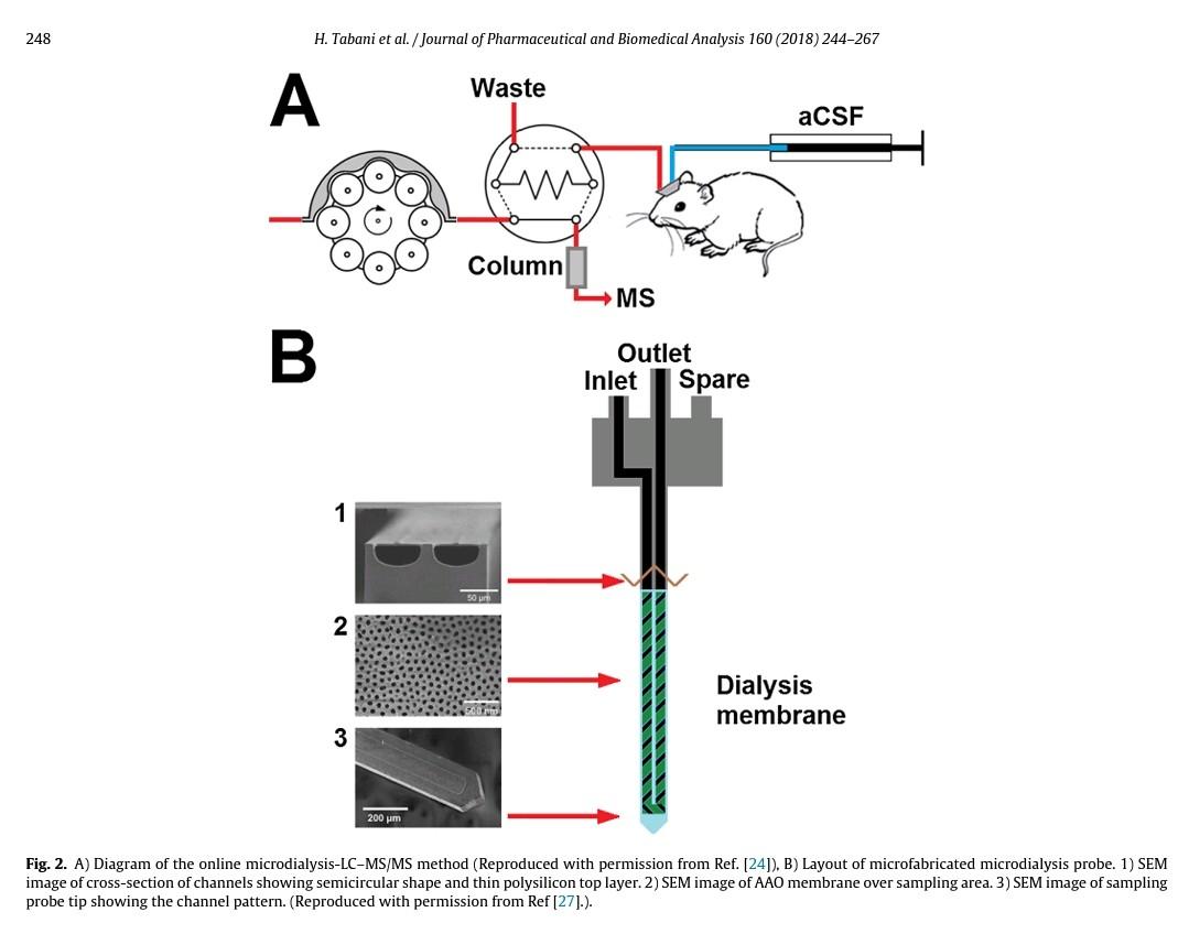
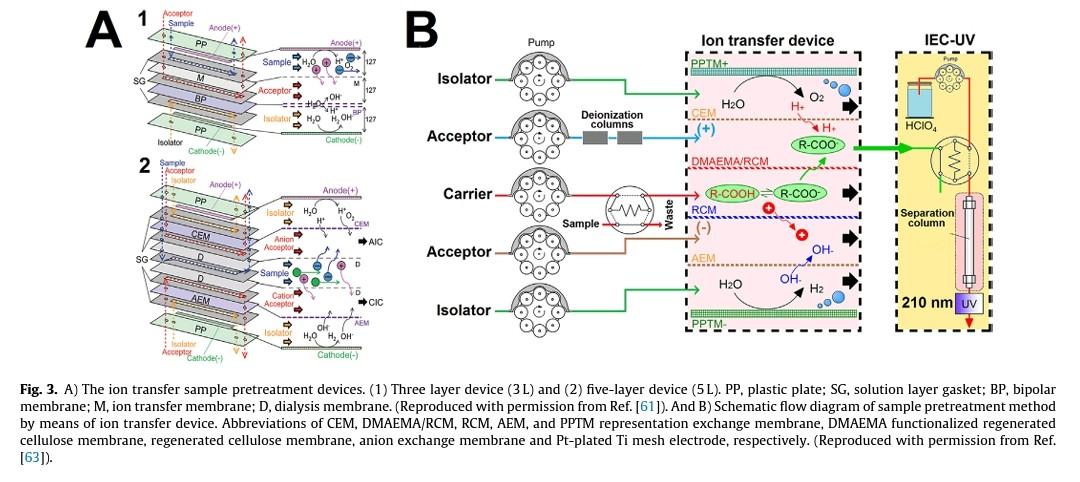
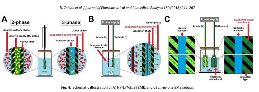
Can you please give brief informations about all of these figures one by one on the subject of membrane processes in pharmaceutical industry?
Fig. 1. Schematic illustration of A) Dialysis, B) Electrodialysis, and C) Filtration. 248 H. Tabani et al. / Iournal of Pharmaceutical and Biomedical Analvsis 160 (2018) 244-267 image of cross-section of channels showing semicircular shape and thin polysilicon top layer. 2) SEM image of AAO membrane over sampling area. 3) SEM image of sampling probe tip showing the channel pattern. (Reproduced with permission from Ref [27].). Fig. 3. A) The ion transfer sample pretreatment devices. (1) Three layer device (3L) and (2) five-layer device (5L). PP, plastic plate; SG, solution layer gasket; BP, bipolar membrane; M, ion transfer membrane; D, dialysis membrane. (Reproduced with permission from Ref. [61]). And B) Schematic flow diagram of sample pretreatment method by means of ion transfer device. Abbreviations of CEM, DMAEMA/RCM, RCM, AEM, and PPTM representation exchange membrane, DMAEMA functionalized regenerated cellulose membrane, regenerated cellulose membrane, anion exchange membrane and Pt-plated Ti mesh electrode, respectively. (Reproduced with permission from Ref. [63]). H. Tabani et al. / Journal of Pharmaceutical and Biomedical Analysis 160 (2018) 244-267 Fig. 4. Schematic illustration of A) HF-LPME, B) EME, and C) all-in-one EME setups. Bulk liquid membrane Acceptor phase Stirrer Donor phase Acceptor phase Un-supported (free) liquid membrane Donor phase Inert tube 1 Anode (+) Cathode (-) + Cathode (-) Fig. 5. Schematic illustration of A) BLM, and B) FLM. Fig. 1. Schematic illustration of A) Dialysis, B) Electrodialysis, and C) Filtration. 248 H. Tabani et al. / Iournal of Pharmaceutical and Biomedical Analvsis 160 (2018) 244-267 image of cross-section of channels showing semicircular shape and thin polysilicon top layer. 2) SEM image of AAO membrane over sampling area. 3) SEM image of sampling probe tip showing the channel pattern. (Reproduced with permission from Ref [27].). Fig. 3. A) The ion transfer sample pretreatment devices. (1) Three layer device (3L) and (2) five-layer device (5L). PP, plastic plate; SG, solution layer gasket; BP, bipolar membrane; M, ion transfer membrane; D, dialysis membrane. (Reproduced with permission from Ref. [61]). And B) Schematic flow diagram of sample pretreatment method by means of ion transfer device. Abbreviations of CEM, DMAEMA/RCM, RCM, AEM, and PPTM representation exchange membrane, DMAEMA functionalized regenerated cellulose membrane, regenerated cellulose membrane, anion exchange membrane and Pt-plated Ti mesh electrode, respectively. (Reproduced with permission from Ref. [63]). H. Tabani et al. / Journal of Pharmaceutical and Biomedical Analysis 160 (2018) 244-267 Fig. 4. Schematic illustration of A) HF-LPME, B) EME, and C) all-in-one EME setups. Bulk liquid membrane Acceptor phase Stirrer Donor phase Acceptor phase Un-supported (free) liquid membrane Donor phase Inert tube 1 Anode (+) Cathode (-) + Cathode (-) Fig. 5. Schematic illustration of A) BLM, and B) FLMStep by Step Solution
There are 3 Steps involved in it
Step: 1

Get Instant Access to Expert-Tailored Solutions
See step-by-step solutions with expert insights and AI powered tools for academic success
Step: 2

Step: 3

Ace Your Homework with AI
Get the answers you need in no time with our AI-driven, step-by-step assistance
Get Started


