

Answered step by step
Verified Expert Solution
Question
1 Approved Answer
Can you run this program on labview and show me the steps by steps on how to do it 1. Launch LabVIEW. Click on Blank
Can you run this program on labview and show me the steps by steps on how to do it 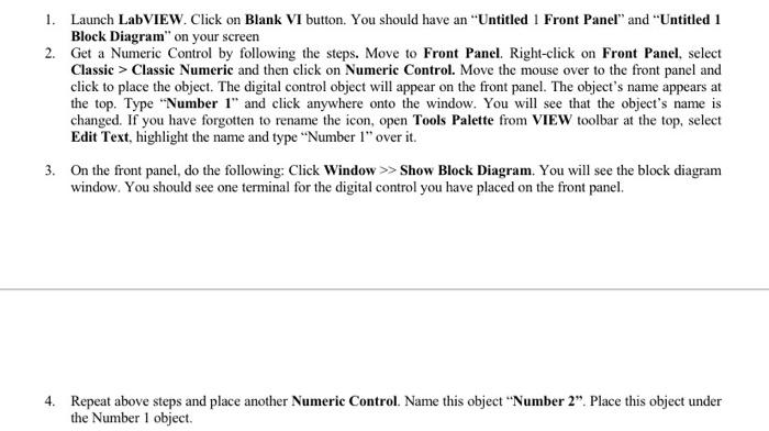
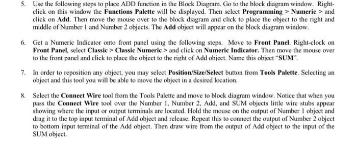
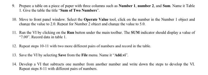
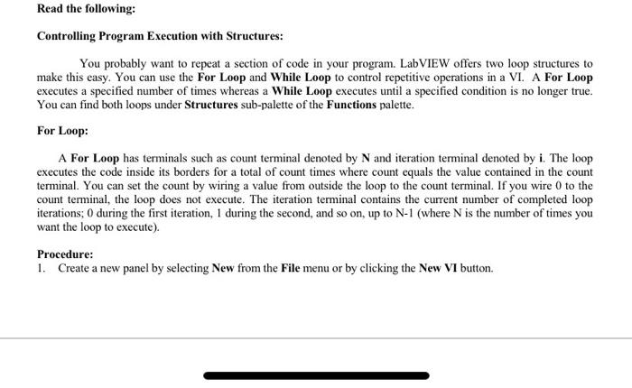
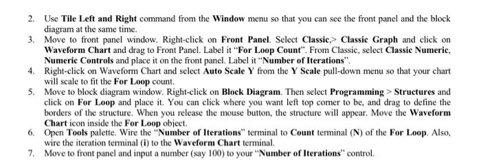
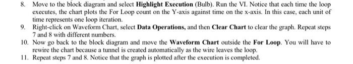
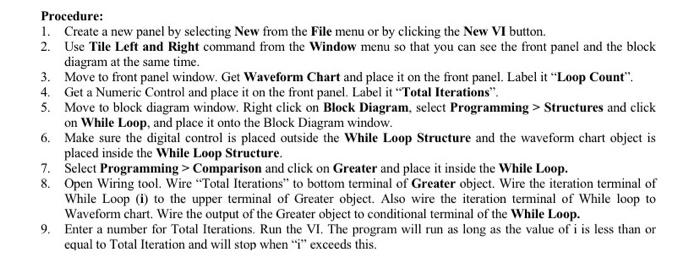
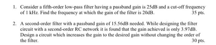 1. Launch LabVIEW. Click on Blank VI button. You should have an "Untitled 1 Front Panel" and "Untitled 1 Block Diagram" on your screen 2. Get a Numeric Control by following the steps. Move to Front Panel. Right click on Front Panel, select Classic > Classic Numeric and then click on Numeric Control. Move the mouse over to the front panel and click to place the object. The digital control object will appear on the front panel. The object's name appears at the top. Type "Number 1" and click anywhere onto the window. You will see that the object's name is changed. If you have forgotten to rename the icon, open Tools Palette from VIEW toolbar at the top, select Edit Text, highlight the name and type "Number 1" over it. 3. On the front panel, do the following: Click Window >> Show Block Diagram. You will see the block diagram window. You should see one terminal for the digital control you have placed on the front panel. 4. Repeat above steps and place another Numeric Control. Name this object "Number 2". Place this object under the Number 1 object 5. Use the following steps to place ADD function in the Block Diagram. Go to the block diagram window. Right- click on this window the Functions Palette will be displayed. Then select Programming > Numeric > and click on Add. Then move the mouse over to the block diagram and click to place the object to the right and middle of Number 1 and Number 2 objects. The Add object will appear on the block diagram window. 6. Get a Numeric Indicator onto front panel using the following steps. Move to Front Panel. Right-clock on Front Panel, select Classic > Classic Numeric > and click on Numeric Indicator. Then move the mouse over to the front panel and click to place the object to the right of Add object. Name this object "SUM". 7. In order to reposition any object, you may select Position/Size/Select button from Tools Palette. Selecting an object and this tool you will be able to move the object in a desired location. 8. Select the Connect Wire tool from the Tools Palette and move to block diagram window. Notice that when you pass the Connect Wire tool over the Number 1, Number 2, Add, and SUM objects little wire stubs appear showing where the input or output terminals are located. Hold the mouse on the output of Number 1 object and drag it to the top input terminal of Add object and release. Repeat this to connect the output of Number 2 object to bottom input terminal of the Add object. Then draw wire from the output of Add object to the input of the SUM object. 9. Prepare a table on a piece of paper with three columns such as Number 1, number 2 and Sum. Name it Table 1. Give the table the title "Sum of Two Numbers". 10. Move to front panel window. Select the Operate Value tool, click on the number in the Number 1 object and change the value to 2.0. Repeat for Number 2 object and change the value to 5.0. 11. Run the VI by clicking on the Run button under the main toolbar. The SUM indicator should display a value of "7.00". Record data in table 1. 12. Repeat steps 10-11 with two more different pairs of numbers and record in the table. 13. Save the VI by selecting Save from the File menu. Name it "Add.vi". 14. Develop a VI that subtracts one number from another number and write down the steps to develop the VI. Repeat steps 8-11 with different pairs of numbers. Read the following: Controlling Program Execution with Structures: You probably want to repeat a section of code in your program. LabVIEW offers two loop structures to make this easy. You can use the For Loop and While Loop to control repetitive operations in a VI. A For Loop executes a specified number of times whereas a While Loop executes until a specified condition is no longer true. You can find both loops under Structures sub-palette of the Functions palette. For Loop: A For Loop has terminals such as count terminal denoted by N and iteration terminal denoted by i. The loop executes the code inside its borders for a total of count times where count equals the value contained in the count terminal. You can set the count by wiring a value from outside the loop to the count terminal. If you wire 0 to the count terminal, the loop does not execute. The iteration terminal contains the current number of completed loop iterations:0 during the first iteration, 1 during the second, and so on, up to N-1 (where N is the number of times you want the loop to execute). Procedure: 1. Create a new panel by selecting New from the File menu or by clicking the New VI button. 2. Use Tile Left and Right command from the Window menu so that you can see the front panel and the block diagram at the same time. 3. Move to front panel window. Right click on Front Panel. Select Classic,> Classic Graph and click on Waveform Chart and drag to Front Panel. Label it "For Loop Count". From Classic, select Classic Numeric, Numeric Controls and place it on the front panel. Label it "Number of Iterations". 4. Right-click on Waveform Chart and select Auto Scale Y from the Y Scale pull-down menu so that your chart will scale to fit the For Loop count. 5. Move to block diagram window. Right click on Block Diagram. Then select Programming > Structures and click on For Loop and place it. You can click where you want left top comer to be, and drag to define the borders of the structure. When you release the mouse button, the structure will appear. Move the Waveform Chart icon inside the For Loop object. 6. Open Tools palette. Wire the "Number of Iterations" terminal to Count terminal (N) of the For Loop. Also, wire the iteration terminal (i) to the Waveform Chart terminal. 7. Move to front panel and input a number (say 100) to your "Number of Iterations" control. 8. Move to the block diagram and select Highlight Execution (Bulb). Run the VI. Notice that each time the loop executes, the chart plots the For Loop count on the Y-axis against time on the x-axis. In this case, each unit of time represents one loop iteration. 9. Right-click on Waveform Chart, select Data Operations, and then Clear Chart to clear the graph. Repeat steps 7 and 8 with different numbers. 10. Now go back to the block diagram and move the waveform Chart outside the For Loop. You will have to rewire the chart because a tunnel is created automatically as the wire leaves the loop. 11. Repeat steps 7 and 8. Notice that the graph is plotted after the execution is completed. Procedure: 1. Create a new panel by selecting New from the File menu or by clicking the New VI button. 2. Use Tile Left and Right command from the Window menu so that you can see the front panel and the block diagram at the same time. 3. Move to front panel window. Get Waveform Chart and place it on the front panel. Label it "Loop Count". 4. Get a Numeric Control and place it on the front panel. Label it "Total Iterations". 5. Move to block diagram window. Right click on Block Diagram, select Programming > Structures and click on While Loop, and place it onto the Block Diagram window. 6. Make sure the digital control is placed outside the While Loop Structure and the waveform chart object is placed inside the While Loop Structure. 7. Select Programming > Comparison and click on Greater and place it inside the While Loop. 8. Open Wiring tool. Wire "Total Iterations to bottom terminal of Greater object. Wire the iteration terminal of While Loop (i) to the upper terminal of Greater object. Also wire the iteration terminal of While loop to Waveform chart. Wire the output of the Greater object to conditional terminal of the While Loop. 9. Enter a number for Total Iterations. Run the VI. The program will run as long as the value of i is less than or equal to Total Iteration and will stop when "T" exceeds this. 1. Consider a fifth-order low-pass filter having a passband gain is 25dB and a cut-off frequency of 1 kHz. Find the frequency at which the gain of the filter is 20dB. 35 pts. 2. A second-order filter with a passband gain of 15.56dB needed. While designing the filter circuit with a second-order RC network it is found that the gain achieved is only 3.97dB. Design a circuit which increases the gain to the desired gain without changing the order of the filter 30 pts. 1. Launch LabVIEW. Click on Blank VI button. You should have an "Untitled 1 Front Panel" and "Untitled 1 Block Diagram" on your screen 2. Get a Numeric Control by following the steps. Move to Front Panel. Right click on Front Panel, select Classic > Classic Numeric and then click on Numeric Control. Move the mouse over to the front panel and click to place the object. The digital control object will appear on the front panel. The object's name appears at the top. Type "Number 1" and click anywhere onto the window. You will see that the object's name is changed. If you have forgotten to rename the icon, open Tools Palette from VIEW toolbar at the top, select Edit Text, highlight the name and type "Number 1" over it. 3. On the front panel, do the following: Click Window >> Show Block Diagram. You will see the block diagram window. You should see one terminal for the digital control you have placed on the front panel. 4. Repeat above steps and place another Numeric Control. Name this object "Number 2". Place this object under the Number 1 object 5. Use the following steps to place ADD function in the Block Diagram. Go to the block diagram window. Right- click on this window the Functions Palette will be displayed. Then select Programming > Numeric > and click on Add. Then move the mouse over to the block diagram and click to place the object to the right and middle of Number 1 and Number 2 objects. The Add object will appear on the block diagram window. 6. Get a Numeric Indicator onto front panel using the following steps. Move to Front Panel. Right-clock on Front Panel, select Classic > Classic Numeric > and click on Numeric Indicator. Then move the mouse over to the front panel and click to place the object to the right of Add object. Name this object "SUM". 7. In order to reposition any object, you may select Position/Size/Select button from Tools Palette. Selecting an object and this tool you will be able to move the object in a desired location. 8. Select the Connect Wire tool from the Tools Palette and move to block diagram window. Notice that when you pass the Connect Wire tool over the Number 1, Number 2, Add, and SUM objects little wire stubs appear showing where the input or output terminals are located. Hold the mouse on the output of Number 1 object and drag it to the top input terminal of Add object and release. Repeat this to connect the output of Number 2 object to bottom input terminal of the Add object. Then draw wire from the output of Add object to the input of the SUM object. 9. Prepare a table on a piece of paper with three columns such as Number 1, number 2 and Sum. Name it Table 1. Give the table the title "Sum of Two Numbers". 10. Move to front panel window. Select the Operate Value tool, click on the number in the Number 1 object and change the value to 2.0. Repeat for Number 2 object and change the value to 5.0. 11. Run the VI by clicking on the Run button under the main toolbar. The SUM indicator should display a value of "7.00". Record data in table 1. 12. Repeat steps 10-11 with two more different pairs of numbers and record in the table. 13. Save the VI by selecting Save from the File menu. Name it "Add.vi". 14. Develop a VI that subtracts one number from another number and write down the steps to develop the VI. Repeat steps 8-11 with different pairs of numbers. Read the following: Controlling Program Execution with Structures: You probably want to repeat a section of code in your program. LabVIEW offers two loop structures to make this easy. You can use the For Loop and While Loop to control repetitive operations in a VI. A For Loop executes a specified number of times whereas a While Loop executes until a specified condition is no longer true. You can find both loops under Structures sub-palette of the Functions palette. For Loop: A For Loop has terminals such as count terminal denoted by N and iteration terminal denoted by i. The loop executes the code inside its borders for a total of count times where count equals the value contained in the count terminal. You can set the count by wiring a value from outside the loop to the count terminal. If you wire 0 to the count terminal, the loop does not execute. The iteration terminal contains the current number of completed loop iterations:0 during the first iteration, 1 during the second, and so on, up to N-1 (where N is the number of times you want the loop to execute). Procedure: 1. Create a new panel by selecting New from the File menu or by clicking the New VI button. 2. Use Tile Left and Right command from the Window menu so that you can see the front panel and the block diagram at the same time. 3. Move to front panel window. Right click on Front Panel. Select Classic,> Classic Graph and click on Waveform Chart and drag to Front Panel. Label it "For Loop Count". From Classic, select Classic Numeric, Numeric Controls and place it on the front panel. Label it "Number of Iterations". 4. Right-click on Waveform Chart and select Auto Scale Y from the Y Scale pull-down menu so that your chart will scale to fit the For Loop count. 5. Move to block diagram window. Right click on Block Diagram. Then select Programming > Structures and click on For Loop and place it. You can click where you want left top comer to be, and drag to define the borders of the structure. When you release the mouse button, the structure will appear. Move the Waveform Chart icon inside the For Loop object. 6. Open Tools palette. Wire the "Number of Iterations" terminal to Count terminal (N) of the For Loop. Also, wire the iteration terminal (i) to the Waveform Chart terminal. 7. Move to front panel and input a number (say 100) to your "Number of Iterations" control. 8. Move to the block diagram and select Highlight Execution (Bulb). Run the VI. Notice that each time the loop executes, the chart plots the For Loop count on the Y-axis against time on the x-axis. In this case, each unit of time represents one loop iteration. 9. Right-click on Waveform Chart, select Data Operations, and then Clear Chart to clear the graph. Repeat steps 7 and 8 with different numbers. 10. Now go back to the block diagram and move the waveform Chart outside the For Loop. You will have to rewire the chart because a tunnel is created automatically as the wire leaves the loop. 11. Repeat steps 7 and 8. Notice that the graph is plotted after the execution is completed. Procedure: 1. Create a new panel by selecting New from the File menu or by clicking the New VI button. 2. Use Tile Left and Right command from the Window menu so that you can see the front panel and the block diagram at the same time. 3. Move to front panel window. Get Waveform Chart and place it on the front panel. Label it "Loop Count". 4. Get a Numeric Control and place it on the front panel. Label it "Total Iterations". 5. Move to block diagram window. Right click on Block Diagram, select Programming > Structures and click on While Loop, and place it onto the Block Diagram window. 6. Make sure the digital control is placed outside the While Loop Structure and the waveform chart object is placed inside the While Loop Structure. 7. Select Programming > Comparison and click on Greater and place it inside the While Loop. 8. Open Wiring tool. Wire "Total Iterations to bottom terminal of Greater object. Wire the iteration terminal of While Loop (i) to the upper terminal of Greater object. Also wire the iteration terminal of While loop to Waveform chart. Wire the output of the Greater object to conditional terminal of the While Loop. 9. Enter a number for Total Iterations. Run the VI. The program will run as long as the value of i is less than or equal to Total Iteration and will stop when "T" exceeds this. 1. Consider a fifth-order low-pass filter having a passband gain is 25dB and a cut-off frequency of 1 kHz. Find the frequency at which the gain of the filter is 20dB. 35 pts. 2. A second-order filter with a passband gain of 15.56dB needed. While designing the filter circuit with a second-order RC network it is found that the gain achieved is only 3.97dB. Design a circuit which increases the gain to the desired gain without changing the order of the filter 30 pts
Step by Step Solution
There are 3 Steps involved in it
Step: 1

Get Instant Access to Expert-Tailored Solutions
See step-by-step solutions with expert insights and AI powered tools for academic success
Step: 2

Step: 3
Ace Your Homework with AI
Get the answers you need in no time with our AI-driven, step-by-step assistance
Get Started
Power Bi And Azure Integrating Cloud Analytics For Scalable Solutions
Authors: Kiet Huynh
1st Edition
B0CMHKB85L, 979-8868959943