Question
CCS coding: main.c to edit on (this one is close but not working as desired): #include msp.h /** * main.c */ void main ( void
CCS coding: 
main.c to edit on (this one is close but not working as desired):
#include "msp.h"
/**
* main.c
*/
void main(void)
{
WDT_A->CTL = WDT_A_CTL_PW | WDT_A_CTL_HOLD; // stop watchdog timer
//Configuring Button1 to be an input with internal pull-up resistors enabled
P1->DIR &= ~BIT1;
P1->REN |= BIT1;
P1->OUT |= BIT1;
//Configuring Button2 to be an input with internal pull-up resistors enabled
P1->DIR &= ~BIT4;
P1->REN |= BIT4;
P1->OUT |= BIT4;
//Configuring RGBLED_RED to be an output
P2->DIR |= BIT0;
//Configuring RGBLED_GREEN to be an output
P2->DIR |= BIT1;
//Configuring RGBLED_BLUE to be an output
P2->DIR |= BIT2;
while (1)
{
int state = 4;
if ((P1->IN & BIT1 ) == 0) // if Button1 is pressed
{
if ((P1->IN & BIT4 ) == 0 && state == 4) // if Button2 is pressed
{
P2->OUT |= BIT0; //Turn RED on
state = 1;
}
}
if ((P1->IN & BIT1 ) == 0) // if Button1 is pressed
{
if ((P1->IN & BIT4 ) == 0 && state == 1) // if Button2 is pressed
{
P2->OUT &= ~BIT0; //Turn RED off
P2->OUT |= BIT1; //Turn GREEN on
state = 2;
}
}
if ((P1->IN & BIT1 ) == 0) // if Button1 is pressed
{
if ((P1->IN & BIT4 ) == 0 && state == 2) // if Button2 is pressed
{
P2->OUT &= ~BIT1; //Turn GREEN off
P2->OUT |= BIT2; //Turn BLUE on
state = 3;
}
}
if ((P1->IN & BIT1 ) == 0) // if Button1 is pressed
{
if ((P1->IN & BIT4 ) == 0 && state == 3) // if Button2 is pressed
{
P2->OUT &= ~BIT2; //Turn BLUE off
state = 4;
}
}
}
}
;
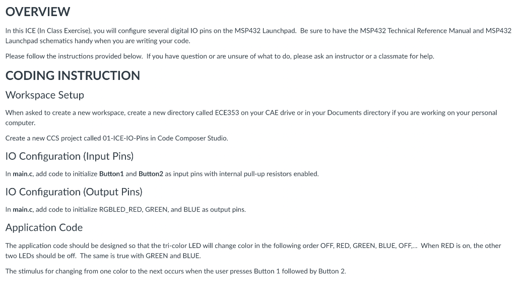
OVERVIEW In this ICE (In Class Exercise), you will configure several digital 10 pins on the MSP432 Launchpad. Be sure to have the MSP432 Technical Reference Manual and MSP432 Launchpad schematics handy when you are writing your code. Please follow the instructions provided below. If you have question or are unsure of what to do, please ask an instructor or a classmate for help. CODING INSTRUCTION Workspace Setup When asked to create a new workspace, create a new directory called ECE353 on your CAE drive or in your Documents directory if you are working on your personal computer. Create a new CCS project called 01-ICE-IO-Pins in Code Composer Studio. 10 Configuration (Input Pins) In main.c, add code to initialize Button 1 and Button2 as input pins with internal pull-up resistors enabled. IO Configuration (Output Pins) In main.c, add code to initialize RGBLED_RED, GREEN, and BLUE as output pins, Application Code The application code should be designed so that the tri-color LED will change color in the following order OFF, RED, GREEN, BLUE, OFF.... When RED is on the other two LEDs should be off. The same is true with GREEN and BLUE. The stimulus for changing from one color to the next occurs when the user presses Button 1 followed by Button 2
Step by Step Solution
There are 3 Steps involved in it
Step: 1

Get Instant Access to Expert-Tailored Solutions
See step-by-step solutions with expert insights and AI powered tools for academic success
Step: 2

Step: 3

Ace Your Homework with AI
Get the answers you need in no time with our AI-driven, step-by-step assistance
Get Started


