

Question
Ch9 LAB Configuring RIPv2 (Packet Tracer) Objective The overall objective of this lab is to configure RIPv2 routing between two routers so that there is
Ch9 LAB Configuring RIPv2 (Packet Tracer)
Objective
The overall objective of this lab is to configure RIPv2 routing between two routers so that there is a routed network connection between computers in the two LANs. This will require that the serial connection between routers be configured and enabled.
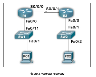
Figure 1 Network Topology
| Devices | IP Address | Subnet Mask | Gateway Address |
| PC1 | 192.168.20.1 | 255.255.255.0 | 192.168.20.250 |
| PC2 | 172.16.75.65 | 255.255.255.0 | 172.16.75.250 |
| R1-Fa0/0 | 192.168.20.250 | 255.255.255.0 | ------------------ |
| R1-S0/0/0 | 10.10.100.1 | 255.255.255.0 | ------------------ |
| R2-Fa0/0 | 172.16.75.250 | 255.255.255.0 | ------------------ |
| R2-S0/0/1 | 10.10.100.2 | 255.255.255.0 | ------------------ |
Table 1. Addressing Table
Network Equipment Required
Packet Tracer
1841 Router with HWIC-2T Interface Card
2950-24 Switch
2 Generic Computers
Copper Straight-through Cable
Serial Cable (with DCE on R1)
Lab Procedure and Questions
This document does not need to be submitted at any time, but I suggest you answer all questions below and in detail and for your future reference. I also suggest you include prompts for all commands listed.
NOTE: You may follow the reference materials posted on Canvas. Please note that the video is only meant for reference, not to follow along. The video may or may not cover everything on this lab and may be out of order. Also the lab numberame reference may be different.
Save any switch or router configurations (copy run start command) often and at completion of your lab.
Configure a RIPv2 to the adjacent LAN, LAN1 (with R1, SW1, and PC1) to LAN2 (with R2, SW2, and PC2). Use default for the clock rate on the serial link (DCE interface).
Create provided LAN on Cisco Packet Tracer. Pay close attention to connections, please follow them.
Go to Preferences under the Options menu of Packet Tracer. Ensure that the following are selected:
Show Device Model Names
Show Device Name Labels
Always Show Port Labels
Show Link Lights
Use the PlaceNote feature of the Cisco Packet Tracer software to label all devices (on topology), IP address, Subnet Mask, Gateway Address and MAC address (as appropriate, use table 1).
Configure and name PC1 and PC2.
Use Table 1 for addressing.
Change the names of the PCs to those labeled on the topology. This can be done through the Global Settings under the Config tab (of each PC).
For the two switches, configure the following:
Hostname (to match topology)
Console password to be password1
Enable secret to be password2
vty 0-4 password to be password3
We are done with switch configurations for the rest of the lab (unless you need to troubleshoot, of course).
For the two routers, configure the following:
Hostname (to match topology)
IP addresses (to match Table 1). Enable the interfaces.
Console password to be password1
Enable secret to be password2
vty password to be password3
Configure a RIP V2 route for both the LAN1 and LAN2 routers. Disable automatic summarization. List the router prompt and command used to accomplish this.
Use two commands to verify that the routes are configured as expected. List the commands used. Provide and explain the information on one of the two.
Verify internetwork connectivity.
What is the default clock rate? What command did you use to check it?
Change clock rate to 56000. List the command(s) used.
Use the proper router command to list the network routes stored in LAN1 routers routing table. List the prompt, the command used and the available routes. Are all of the routes defined for your network? What does it mean to say that the Gateway of last resort is not set?
Save all your configurations. Use the proper command to verify the configuration has been saved to NVRAM. What command did you use?
So/0/0 so/o/1 SO/0/1 R1 R2 Fa0/0 Fa0/0 Fa0/11 Fa0/1 SW1 SW2 Fa0/1 Fa0/2 PC1 PC2 Figure 1 Network Topology So/0/0 so/o/1 SO/0/1 R1 R2 Fa0/0 Fa0/0 Fa0/11 Fa0/1 SW1 SW2 Fa0/1 Fa0/2 PC1 PC2 Figure 1 Network Topology
Step by Step Solution
There are 3 Steps involved in it
Step: 1

Get Instant Access to Expert-Tailored Solutions
See step-by-step solutions with expert insights and AI powered tools for academic success
Step: 2

Step: 3
Ace Your Homework with AI
Get the answers you need in no time with our AI-driven, step-by-step assistance
Get Started
Database Technology And Management Computers And Information Processing Systems For Business
Authors: Robert C. Goldstein
1st Edition
0471887374, 978-0471887379