

Answered step by step
Verified Expert Solution
Question
1 Approved Answer
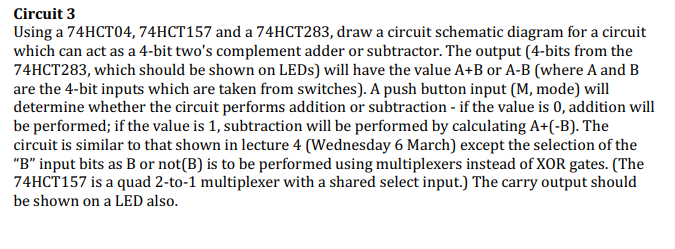
Circuit 3 Using a 74HCT04, 74HCT157 and a 74HCT283, draw a circuit schematic diagram for a circuit which can act as a 4-bit two's complement
Step by Step Solution
There are 3 Steps involved in it
Step: 1

Get Instant Access to Expert-Tailored Solutions
See step-by-step solutions with expert insights and AI powered tools for academic success
Step: 2

Step: 3
Ace Your Homework with AI
Get the answers you need in no time with our AI-driven, step-by-step assistance
Get Started
Advances In Databases And Information Systems 15th International Conference Adbis 2011 Vienna Austria September 2011 Proceedings Lncs 6909
Authors: Johann Eder ,Maria Bielikova ,A Min Tjoa
2011th Edition
3642237363, 978-3642237362