

Answered step by step
Verified Expert Solution
Question
1 Approved Answer
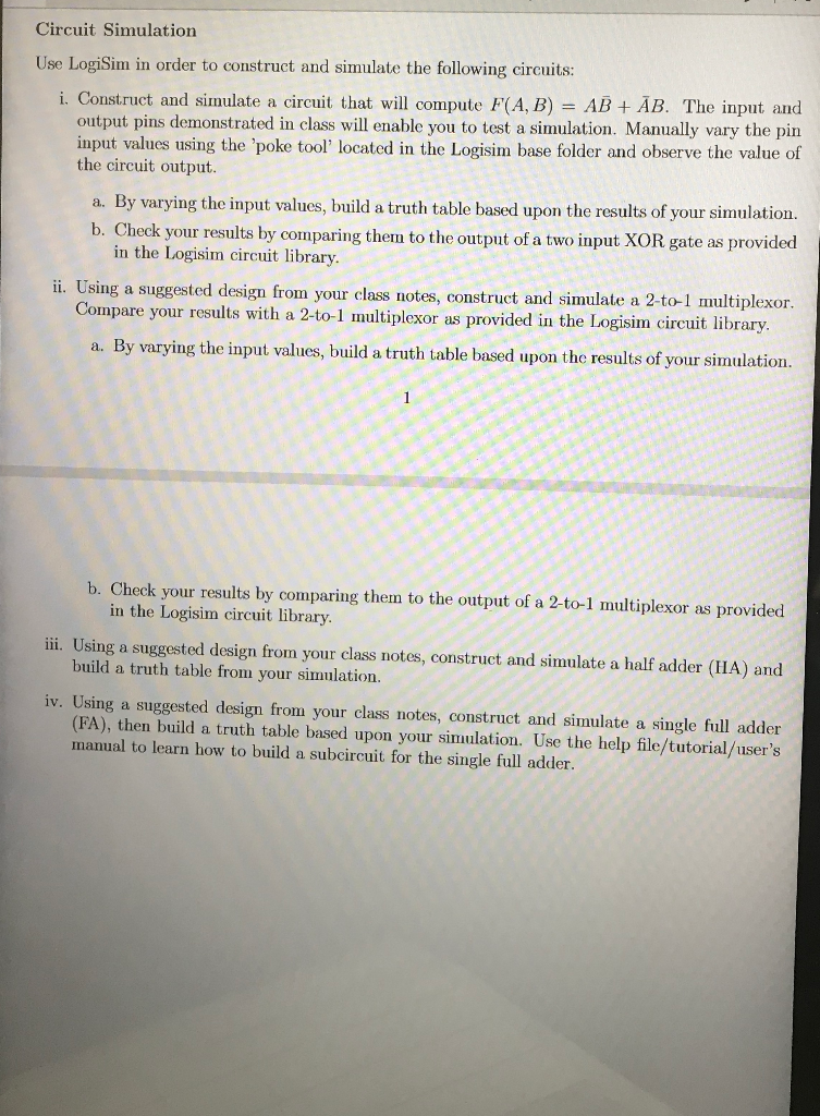
Circuit Simulation Use LogiSim in order to construct and simulate the following circuits: i. Construct and simulate a circuit that will compute F(A,B) = AB
Step by Step Solution
There are 3 Steps involved in it
Step: 1

Get Instant Access to Expert-Tailored Solutions
See step-by-step solutions with expert insights and AI powered tools for academic success
Step: 2

Step: 3
Ace Your Homework with AI
Get the answers you need in no time with our AI-driven, step-by-step assistance
Get Started
SQL Server 2019 Administrator S Guide A Definitive Guide For DBAs To Implement Monitor And Maintain Enterprise Database Solutions
Authors: Marek Chmel ,Vladimir Muzny
2nd Edition
1789954320, 978-1789954326