

Question: cisco packet tracer 1 / 9 100% + Laboratory Project II IOS Networking Essentials This laboratory project introduces students to simple iOS networking tasks such
 cisco packet tracer
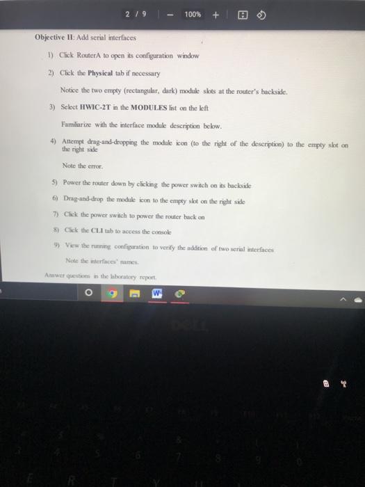


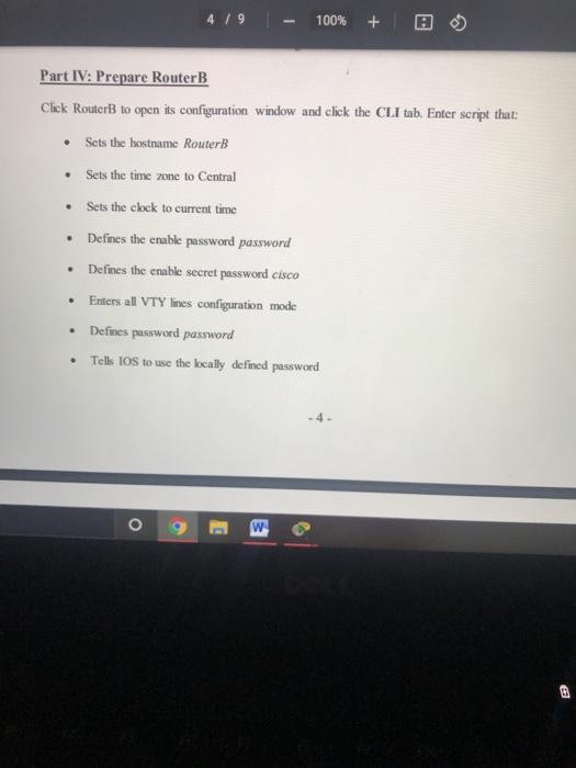
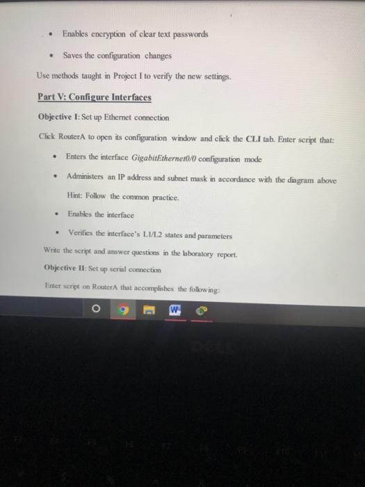

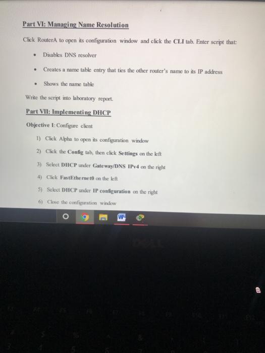
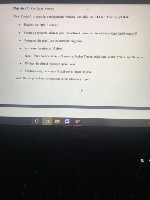
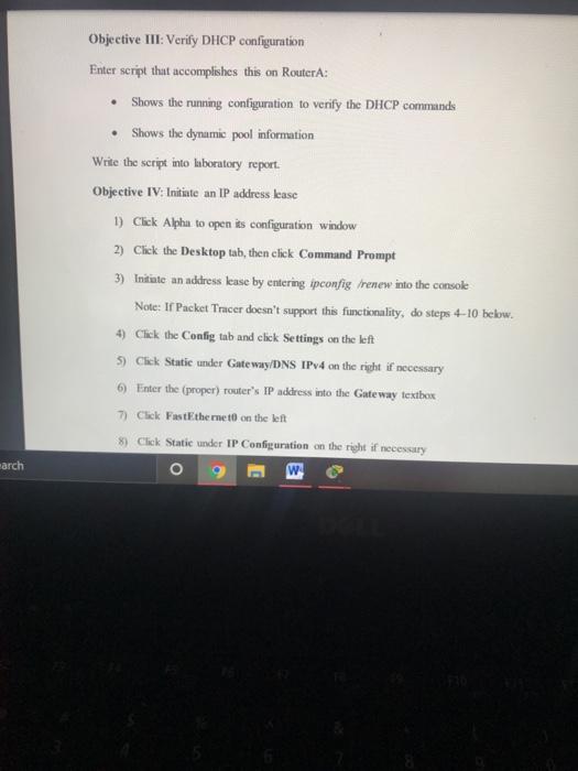
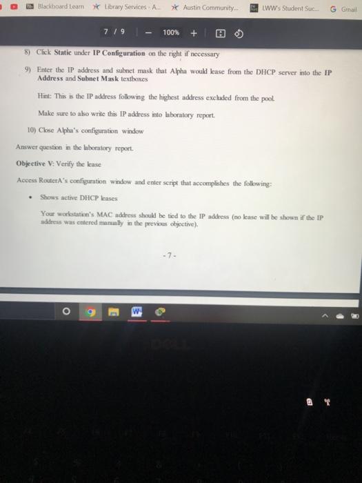
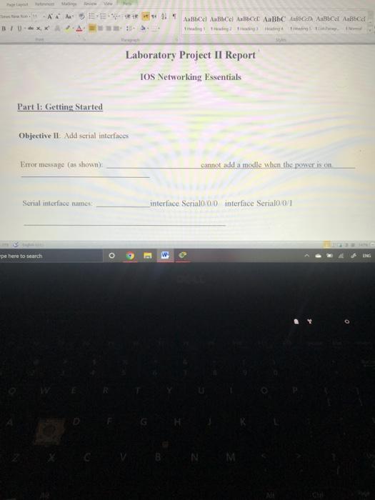


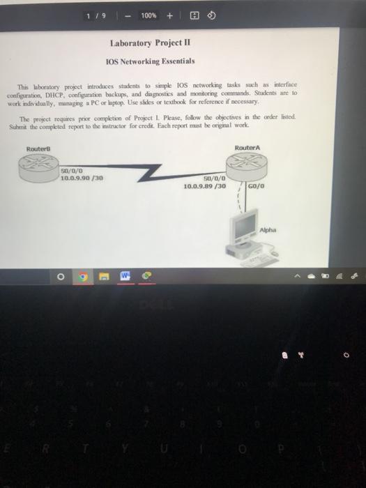
1 / 9 100% + Laboratory Project II IOS Networking Essentials This laboratory project introduces students to simple iOS networking tasks such as interface configuration, DHCP, configuration backups, and diagnostics and monitoring commands. Students are to work individually, managing a PC or laptop. Lise slides or textbook for reference if necessary The project requires pour completion of Project 1. Please, follow the objectives in the order listed. Suunt the completed report to the instructor for credit. Each report must be original work Router Router SD/0/0 10.0.9.90 /30 Su/0/0 10.0.9.89 /30 GO/0 O 2 / 9 100% Objective II: Add serial interfaces 1) Click Router to open its configuration window 2). Click the Physical tab if necessary Notice the two empty (rectangular, dark) module skots at the router's backside. 3) Select HIWIC-2T in the MODULES list on the left Familiarize with the interface moduk description below. 4) Attempt drag-and-dropping the module icon (to the right of the description) to the emply skt on the right side Note the error 5) Power the router down by clicking the power switch on is backside 6) Drag and drop the module icon to the empty sket on the right side 7) Chek the power swach to power the router back on 8) Click the Cultub to access the console 9) View the running configuration to verify the addition of two serial interfaces Note the resume Anwer questions in the laboratory report o C Answer questions in the laboratory report. Part II: Learning Interface Defaults Objective 1: Stay Ethernet defaults Enter command on Router that reports the status and parameters of the interface Gigabit Ethernet0/0 What's the interface's Physical and Data Link layers' default state? Interpret the state shown. Is the MAC address shown? What are the IP address and subnet mask? What's the MTU sire? O B 3 What's the interface's default bandwidth and delay? Write the command and answer questions in the laboratory report. Objective II: Study serial defaults Enter a command on RouterA that reports the status and parameters of the interface Serial0/0/0. What's the interface's Physical and Data Link layers' state? Is a MAC address shown? What are the IP address and subset mask? What's the MTU sive? What's the interface's bandwidth and delay? What's the default L2 protocol Write the command and answer questions in the laboratory report Part III: Construct Network Objective L Add second router 1) In the Packet Tracer window, press Ctrl+ARR to select the Network Devices Routers group ch o Part III: Construct Network Objective : Add second router 1) In the Packet Tracer window, press Ctrl+All+R to select the Network Devices/Routers group 2) In the router selection ribbon, click the 1941 icon, then click white space to the RouterA's left 3) Click the new router to open its configuration window 4) Click the Physical tab if necessary 5) Select HWIC-2T in the MODULES list on the left 6) Power the router down by clicking the power switch on is backside 7) Drag-and-drop the module icon to the empty skot on the right side 8) Click the power switch to perwer the router back on 9) Click the Config tuh, then enter Router into the Display Name textbox The new router now has two serial interfaces and all Cisco factory default settings, O W Blackboard Learn Library Services 4 / 9 100% + Objective II: Add Alpha 1) In the Packet Tracer window. press Ctrl+Alt+V to select the End Devices group 2) In the devices ribbon, click the Server icon, then click white space below RouterA 3) Click the new server to open its configuration window 4) Click the Config tab, then enter Alpha into the Display Name textbox The server has a number of usable services; it can be also used as another host on the network Objective III: Connect cables 1) In the Packet Tracer window, press Ctrl+AltO to select the Connections group 2) In the cable selection ribbon, click the Copper Cross-Over icon 3) Click RouterA and select GigabitEthernet0/0 in the connections list 4) Click Alpha and select FastEthernet 5) In the cable selection ribbon, click Serial DCE 6) Click Roster and select Serial0/0/0 in the list 7) Click Router and select Serial0/0/0 in the list The network should now look similar to the desgram. Red Drama O w 4. / 9 100% + Part IV: Prepare RouterB Click RouterB to open its configuration window and click the CLI tab. Enter script that: Sets the hostname RouterB Sets the time zone to Central Sets the clock to current time Defines the enable password password Defines the enable secret password cisco Enters all VTY Ines configuration mode Defines password password Tells IOS to use the bcally defined password w 0 Enables encryption of clear text passwords Saves the configuration changes Use methods taught in Project I to verify the new settings. Part V: Configure Interfaces Objective 1: Set up Ethernet connection Click RouterA to open its configuration window and click the CLI tab. Enter script that: Enters the interface GigabitEthernet0/0 configuration mode Administers an IP address and subnet mask in accordance with the diagram above Hint: Follow the common practice. Enables the interface Verifies the interface's L1/L2 states and parameters Write the script and answer questions in the laboratory report. Objective II: Set up serial connection Enter script on-Router that accomplishes the following: W O . Objective II: Set up serial connection Enter script on Router that accomplishes the following: Enters interface Serial0/0/0 configuration mode Administers the IP address and subnet mask shown on the diagram Sets PPP as L2 protocol Sets clock rate to 56,000 baud Sets bandwidth to 1,544 Kbps Sets the MTU size to 17,000 bytes Enables the interface Verifies the interface's L1/L2 states and parameters Note: The MTU size may be shown incorrectly in Packet Tracer, ignore it. Write the script and answer questions in the laboratory report. Repeat this objective's script on RouterB. . . o g E w Part VI: Managing Name Resolution Click Router to open its configuration window and click the CLI tab. Enter script that: Disables DNS resolver Creates a name table entry that ties the other router's name to its IP address Shows the name table Write the script into laboratory report. Part VII: Implementing DHCP Objective I: Configure client 1) Click Alphu to open its configuration window 2) Click the Config tab, then click Settings on the left 3) Select DHCP under Gateway/DNS IPv4 on the right 4) Click FastEthernet on the left 5) Select DHCP under IP configuration on the right Close the configuration window 9 w . Objective I: Configure service Click Router to open its configuration window and click the CLI tab. Enter script that: Enables the DHCP service Creates a dynamic address pool for network connected to interface GigabitEthernet0/0 Populates the pool (use the network diagram) Sets lease duration to 15 days Note: If this command doesn't work in Packet Tracer, make sure to still write it into the report. Defines the default gateway option value Excludes only necessary IP address(es) from the pool Write the script and answer question in the laboratory report. . -6. O g B Objective III: Verify DHCP configuration Enter script that accomplishes this on RouterA: Shows the running configuration to verify the DHCP commands Shows the dynamic pool information Write the script into laboratory report. Objective IV: Initiate an IP address lease 1) Click Alpha to open its configuration window 2) Click the Desktop tab, then click Command Prompt 3) Initiate an address lease by entering ipconfig renew into the console Note: If Packet Tracer doesn't support this functionality, do steps 4-10 below. 4) Click the Config tab and click Settings on the left 5) Click Static under Gateway/DNS IPv4 on the right if necessary 6) Enter the (proper) router's IP address into the Gateway textbox 7) Click FastEthemet on the left 8) Click Static under IP Configuration on the right if necessary o w earch Blackboard Learn Library Services A. Austin Community... LWW's Student Suc... G Gmail 7/9 100% + 8) Click Static under IP Configuration on the right if necessary 9) Enter the IP address and subnet mask that Alpha would lease from the DHCP server into the IP Address and Subnet Mask textboxes Hint: This is the IP address following the highest address excluded from the pool Make sure to ako write this IP address into laboratory report 10) Close Alpha's configuration window Answer question in the laboratory report Objective V: Verify the lense Access Router A's configuration window and enter script that accomplishes the following: Shows active DHCP lenses Your workstatie's MAC address should be tied to the IP address (no kase will be shown if the IP address was entered manully in the previous objective) -7- o 9 Shows the statisties on DHCP messages sent and received Note the Discover, Request, Offer, and Acknowledgement message numbers. If this command doesn't work in Packet Tracer, make sure to still write it into the report. Write the script into laboratory report Part VIII: Verifying Communications In RouterA's configuration window: 1) Use ping to verify that Alphus can be reached Note: the ping may fail initially due to the ARP lateney; repeat the ping if necessary 2) Use ping to verify that Router can be reached Notify the instructor of a problem. Answer question in the laboratory report Part IX: Backing Up/Restoring IOS Images & Configurations It's a security best practice to create backup copies of the router 10S images and configuration such a copy can be med to quickly restore the router configuration if it becomes corrupt or configure a replacement router. Cusco los alkws for backing up the files to und restering them from a TFTP server Objective I: Verify TFTP server 1) Click Alpha to open it configuration window o E W Objective 1: Verify TFTP server 1) Click Alpha to open its configuration window 2) Click the Services tab, then click TFTP under SERVICES on the left 3) Verify that On is selected next to Service on the right Objeetive Il Buck up the configuration 1) Click Router A to open is configuration window and click the CLI tab 2) Enter a command to copy the running configuration to Alpha When prompted, enter Alpha's IP address when prompted and accept the default file name. 3) Click Alpha to open its configuration window 4) Click the Services tab, then click TFTP under SERVICES on the left 5) Verify the existence of the configuration copy in the file it (scroll down if necessary) Write the command into laboratory report. o 2 - 100% + Objective III: Restore the configuration In the Router's configuration window, enter a command to replace the startup configuration file with the configuration stored at the TFTP server. Enter the server's IP address when prompted and then enter the file name. Write the command into laboratory report Objective IV: Back up an IOS image 1) In the Router A's configuration window, enter a command to let the flush memory contents Note the 10 image's filename: 2) Enter a command to back up an IOS image to a TFTP server When prompted, enter the IOS image's filename for the source filename, then enter the Alpha's IP address, and then backup image for the destination file name 3) In Alpha's configuration window, click the Services tab, then click TFTP under SERVICES the len 4) Verify the existence of the 105 mage's copy in the file lint (scroll down if necessary) Write the command into laboratory report Objective V: Restoran 105 mage 1) In Roger's configuration window, delete the 10 image from flash by entering the enable mode comand delete Mus:/IOS e Allename use the actual filename noted above) Press Enter to confirm when prompted (may have to press it twice) 9 W Objective V: Restore an IOS image 1) In RouterA's configuration window, delete the IOS image from flash by entering the enable mode command delete flush:70s image filename (use the actual filename noted above) Press Enter to confirm when prompted (may have to press it twice). 2) List the flash memory contents to verify the deletion 3) Enter a command to restore an los image from a TFTP server When prompted, enter the server's IP address, then enter buckup Image for the source filemme, and then enter the same IOS mage's filename as the one deleted. 4) Re-list the flash contents to verify the operation Write the command into laboratory report. Part X: Shutting Down 1) Enter copy at start to save the configuration 2) Save the project by clicking the Save button in the Packet Tracer's toober 3) Close Packet Tracer Tutustu AEE 1 AaBbce Autocel ABC ABC Aubel A Boca BU XA the it Laboratory Project II Report IOS Networking Essentials Part I: Getting Started Objective It Add scrial interfaces Error message (as shown cannot add a modle when the powers on Serial interface names interface Serial0/0/0 interfice Serial0/0/1 pe here to search N M by Model Show 2! ABC ABC ABC Bb C Bbca Antical Part II: Learning Interface Defaults Objective Study Ethernet defaults Command entered: Physical layer's default state (as shown) Interpretation of the Ll state, Data Link layer's default state as shown) Internation of the state ype here to search ENG The New Hon 11 AAA AaBbcel AaBbcc Aa Bb AaBbabe AaBbce Aabbet Ting Theding? The Heading The Ta Interpretation of the L2 state: Is the MAC address shown (yeso)? Default IP address and subnet mask (if any): wpe here to search O E W Bole label BOCCE AaBbc Bbce AaBbce AaBb Cel Theding Ting Ting Heading Trading The Path Default MTU size (bytes); Default parameters: Bandwidth (Kbps): Delay (LS): Objective II: Study serial defaults Command entered Physical layer's default state (as shown): Data Link layer's default state as shown me here to search W 10 ING ront Is a MAC address shown (yeso)? IP address and subnet mask (if any): Default MTU size (bytes): Default parameters: Bandwidth (Kbps): Delay (us): Default Data Link layer protocol: Part V: Configure Interfaces Objective 1 Set up Ethernet connection Script entered: Physical layer's new state (as shown): 2 - Type here to search B Interpretation of the Ll state: Type here to search Times New Rom. 11 AA AaBbCel AaBbcel Aa Bbce Aalblack ABCd AaB 1 Heading Theading 2 Heading Heading 4 1 Hearing List Page Normal | | | - The x x Foot Paragraph Data Link layer's new state (as shown): Interpretation of the L2 state: Are the IP address and subnet mask shown (yeso)? Interface's duplex mode: Objective II Set up serial connection Script entered Objective II: Set up serial connection Script entered: Part VI: Managing Name Resolution Script entered Type here to search w Part VII: Implementing DHCP Objective II: Configure service Script entered: AnkTools lab2_report compatibility Mode) - Microsoft Word Page Layout References Mailings Review View Times New Rom13 ANAN BI Ue , X AaBb Cel AaBbCel Aa Bbcc Aa Bbc AaBb Di AaB Heading Heading 2 Heading 3 Heading 4 Tading Sust Style Voet Patah Justify the choice of IP address for the default gateway option: For each IP address excluded from the dynamic pool, explain why it's excluded: BIU - x Paragraph Objective III: Verify DHCP configuration Script entered: Objective IV: Initiate an IP address lease IP address obtained Objective V: Verify the lease Script entered Type here to search o W Part VIII: Verifying Communications 14 ad Ping destination addresses med Part IX: Backing Up/Restoring IOS Images & Configurations Objective II Back up the configuration Command entered Objective III Restore the configuration Command cred Type here to search o 3 NM Objective IV Back up an OS image Command entered Objective V Restore an OS image Command to restore an image: Type here to search o 1 / 9 100% + Laboratory Project II IOS Networking Essentials This laboratory project introduces students to simple iOS networking tasks such as interface configuration, DHCP, configuration backups, and diagnostics and monitoring commands. Students are to work individually, managing a PC or laptop. Lise slides or textbook for reference if necessary The project requires pour completion of Project 1. Please, follow the objectives in the order listed. Suunt the completed report to the instructor for credit. Each report must be original work Router Router SD/0/0 10.0.9.90 /30 Su/0/0 10.0.9.89 /30 GO/0 O 2 / 9 100% Objective II: Add serial interfaces 1) Click Router to open its configuration window 2). Click the Physical tab if necessary Notice the two empty (rectangular, dark) module skots at the router's backside. 3) Select HIWIC-2T in the MODULES list on the left Familiarize with the interface moduk description below. 4) Attempt drag-and-dropping the module icon (to the right of the description) to the emply skt on the right side Note the error 5) Power the router down by clicking the power switch on is backside 6) Drag and drop the module icon to the empty sket on the right side 7) Chek the power swach to power the router back on 8) Click the Cultub to access the console 9) View the running configuration to verify the addition of two serial interfaces Note the resume Anwer questions in the laboratory report o C Answer questions in the laboratory report. Part II: Learning Interface Defaults Objective 1: Stay Ethernet defaults Enter command on Router that reports the status and parameters of the interface Gigabit Ethernet0/0 What's the interface's Physical and Data Link layers' default state? Interpret the state shown. Is the MAC address shown? What are the IP address and subnet mask? What's the MTU sire? O B 3 What's the interface's default bandwidth and delay? Write the command and answer questions in the laboratory report. Objective II: Study serial defaults Enter a command on RouterA that reports the status and parameters of the interface Serial0/0/0. What's the interface's Physical and Data Link layers' state? Is a MAC address shown? What are the IP address and subset mask? What's the MTU sive? What's the interface's bandwidth and delay? What's the default L2 protocol Write the command and answer questions in the laboratory report Part III: Construct Network Objective L Add second router 1) In the Packet Tracer window, press Ctrl+ARR to select the Network Devices Routers group ch o Part III: Construct Network Objective : Add second router 1) In the Packet Tracer window, press Ctrl+All+R to select the Network Devices/Routers group 2) In the router selection ribbon, click the 1941 icon, then click white space to the RouterA's left 3) Click the new router to open its configuration window 4) Click the Physical tab if necessary 5) Select HWIC-2T in the MODULES list on the left 6) Power the router down by clicking the power switch on is backside 7) Drag-and-drop the module icon to the empty skot on the right side 8) Click the power switch to perwer the router back on 9) Click the Config tuh, then enter Router into the Display Name textbox The new router now has two serial interfaces and all Cisco factory default settings, O W Blackboard Learn Library Services 4 / 9 100% + Objective II: Add Alpha 1) In the Packet Tracer window. press Ctrl+Alt+V to select the End Devices group 2) In the devices ribbon, click the Server icon, then click white space below RouterA 3) Click the new server to open its configuration window 4) Click the Config tab, then enter Alpha into the Display Name textbox The server has a number of usable services; it can be also used as another host on the network Objective III: Connect cables 1) In the Packet Tracer window, press Ctrl+AltO to select the Connections group 2) In the cable selection ribbon, click the Copper Cross-Over icon 3) Click RouterA and select GigabitEthernet0/0 in the connections list 4) Click Alpha and select FastEthernet 5) In the cable selection ribbon, click Serial DCE 6) Click Roster and select Serial0/0/0 in the list 7) Click Router and select Serial0/0/0 in the list The network should now look similar to the desgram. Red Drama O w 4. / 9 100% + Part IV: Prepare RouterB Click RouterB to open its configuration window and click the CLI tab. Enter script that: Sets the hostname RouterB Sets the time zone to Central Sets the clock to current time Defines the enable password password Defines the enable secret password cisco Enters all VTY Ines configuration mode Defines password password Tells IOS to use the bcally defined password w 0 Enables encryption of clear text passwords Saves the configuration changes Use methods taught in Project I to verify the new settings. Part V: Configure Interfaces Objective 1: Set up Ethernet connection Click RouterA to open its configuration window and click the CLI tab. Enter script that: Enters the interface GigabitEthernet0/0 configuration mode Administers an IP address and subnet mask in accordance with the diagram above Hint: Follow the common practice. Enables the interface Verifies the interface's L1/L2 states and parameters Write the script and answer questions in the laboratory report. Objective II: Set up serial connection Enter script on-Router that accomplishes the following: W O . Objective II: Set up serial connection Enter script on Router that accomplishes the following: Enters interface Serial0/0/0 configuration mode Administers the IP address and subnet mask shown on the diagram Sets PPP as L2 protocol Sets clock rate to 56,000 baud Sets bandwidth to 1,544 Kbps Sets the MTU size to 17,000 bytes Enables the interface Verifies the interface's L1/L2 states and parameters Note: The MTU size may be shown incorrectly in Packet Tracer, ignore it. Write the script and answer questions in the laboratory report. Repeat this objective's script on RouterB. . . o g E w Part VI: Managing Name Resolution Click Router to open its configuration window and click the CLI tab. Enter script that: Disables DNS resolver Creates a name table entry that ties the other router's name to its IP address Shows the name table Write the script into laboratory report. Part VII: Implementing DHCP Objective I: Configure client 1) Click Alphu to open its configuration window 2) Click the Config tab, then click Settings on the left 3) Select DHCP under Gateway/DNS IPv4 on the right 4) Click FastEthernet on the left 5) Select DHCP under IP configuration on the right Close the configuration window 9 w . Objective I: Configure service Click Router to open its configuration window and click the CLI tab. Enter script that: Enables the DHCP service Creates a dynamic address pool for network connected to interface GigabitEthernet0/0 Populates the pool (use the network diagram) Sets lease duration to 15 days Note: If this command doesn't work in Packet Tracer, make sure to still write it into the report. Defines the default gateway option value Excludes only necessary IP address(es) from the pool Write the script and answer question in the laboratory report. . -6. O g B Objective III: Verify DHCP configuration Enter script that accomplishes this on RouterA: Shows the running configuration to verify the DHCP commands Shows the dynamic pool information Write the script into laboratory report. Objective IV: Initiate an IP address lease 1) Click Alpha to open its configuration window 2) Click the Desktop tab, then click Command Prompt 3) Initiate an address lease by entering ipconfig renew into the console Note: If Packet Tracer doesn't support this functionality, do steps 4-10 below. 4) Click the Config tab and click Settings on the left 5) Click Static under Gateway/DNS IPv4 on the right if necessary 6) Enter the (proper) router's IP address into the Gateway textbox 7) Click FastEthemet on the left 8) Click Static under IP Configuration on the right if necessary o w earch Blackboard Learn Library Services A. Austin Community... LWW's Student Suc... G Gmail 7/9 100% + 8) Click Static under IP Configuration on the right if necessary 9) Enter the IP address and subnet mask that Alpha would lease from the DHCP server into the IP Address and Subnet Mask textboxes Hint: This is the IP address following the highest address excluded from the pool Make sure to ako write this IP address into laboratory report 10) Close Alpha's configuration window Answer question in the laboratory report Objective V: Verify the lense Access Router A's configuration window and enter script that accomplishes the following: Shows active DHCP lenses Your workstatie's MAC address should be tied to the IP address (no kase will be shown if the IP address was entered manully in the previous objective) -7- o 9 Shows the statisties on DHCP messages sent and received Note the Discover, Request, Offer, and Acknowledgement message numbers. If this command doesn't work in Packet Tracer, make sure to still write it into the report. Write the script into laboratory report Part VIII: Verifying Communications In RouterA's configuration window: 1) Use ping to verify that Alphus can be reached Note: the ping may fail initially due to the ARP lateney; repeat the ping if necessary 2) Use ping to verify that Router can be reached Notify the instructor of a problem. Answer question in the laboratory report Part IX: Backing Up/Restoring IOS Images & Configurations It's a security best practice to create backup copies of the router 10S images and configuration such a copy can be med to quickly restore the router configuration if it becomes corrupt or configure a replacement router. Cusco los alkws for backing up the files to und restering them from a TFTP server Objective I: Verify TFTP server 1) Click Alpha to open it configuration window o E W Objective 1: Verify TFTP server 1) Click Alpha to open its configuration window 2) Click the Services tab, then click TFTP under SERVICES on the left 3) Verify that On is selected next to Service on the right Objeetive Il Buck up the configuration 1) Click Router A to open is configuration window and click the CLI tab 2) Enter a command to copy the running configuration to Alpha When prompted, enter Alpha's IP address when prompted and accept the default file name. 3) Click Alpha to open its configuration window 4) Click the Services tab, then click TFTP under SERVICES on the left 5) Verify the existence of the configuration copy in the file it (scroll down if necessary) Write the command into laboratory report. o 2 - 100% + Objective III: Restore the configuration In the Router's configuration window, enter a command to replace the startup configuration file with the configuration stored at the TFTP server. Enter the server's IP address when prompted and then enter the file name. Write the command into laboratory report Objective IV: Back up an IOS image 1) In the Router A's configuration window, enter a command to let the flush memory contents Note the 10 image's filename: 2) Enter a command to back up an IOS image to a TFTP server When prompted, enter the IOS image's filename for the source filename, then enter the Alpha's IP address, and then backup image for the destination file name 3) In Alpha's configuration window, click the Services tab, then click TFTP under SERVICES the len 4) Verify the existence of the 105 mage's copy in the file lint (scroll down if necessary) Write the command into laboratory report Objective V: Restoran 105 mage 1) In Roger's configuration window, delete the 10 image from flash by entering the enable mode comand delete Mus:/IOS e Allename use the actual filename noted above) Press Enter to confirm when prompted (may have to press it twice) 9 W Objective V: Restore an IOS image 1) In RouterA's configuration window, delete the IOS image from flash by entering the enable mode command delete flush:70s image filename (use the actual filename noted above) Press Enter to confirm when prompted (may have to press it twice). 2) List the flash memory contents to verify the deletion 3) Enter a command to restore an los image from a TFTP server When prompted, enter the server's IP address, then enter buckup Image for the source filemme, and then enter the same IOS mage's filename as the one deleted. 4) Re-list the flash contents to verify the operation Write the command into laboratory report. Part X: Shutting Down 1) Enter copy at start to save the configuration 2) Save the project by clicking the Save button in the Packet Tracer's toober 3) Close Packet Tracer Tutustu AEE 1 AaBbce Autocel ABC ABC Aubel A Boca BU XA the it Laboratory Project II Report IOS Networking Essentials Part I: Getting Started Objective It Add scrial interfaces Error message (as shown cannot add a modle when the powers on Serial interface names interface Serial0/0/0 interfice Serial0/0/1 pe here to search N M by Model Show 2! ABC ABC ABC Bb C Bbca Antical Part II: Learning Interface Defaults Objective Study Ethernet defaults Command entered: Physical layer's default state (as shown) Interpretation of the Ll state, Data Link layer's default state as shown) Internation of the state ype here to search ENG The New Hon 11 AAA AaBbcel AaBbcc Aa Bb AaBbabe AaBbce Aabbet Ting Theding? The Heading The Ta Interpretation of the L2 state: Is the MAC address shown (yeso)? Default IP address and subnet mask (if any): wpe here to search O E W Bole label BOCCE AaBbc Bbce AaBbce AaBb Cel Theding Ting Ting Heading Trading The Path Default MTU size (bytes); Default parameters: Bandwidth (Kbps): Delay (LS): Objective II: Study serial defaults Command entered Physical layer's default state (as shown): Data Link layer's default state as shown me here to search W 10 ING ront Is a MAC address shown (yeso)? IP address and subnet mask (if any): Default MTU size (bytes): Default parameters: Bandwidth (Kbps): Delay (us): Default Data Link layer protocol: Part V: Configure Interfaces Objective 1 Set up Ethernet connection Script entered: Physical layer's new state (as shown): 2 - Type here to search B Interpretation of the Ll state: Type here to search Times New Rom. 11 AA AaBbCel AaBbcel Aa Bbce Aalblack ABCd AaB 1 Heading Theading 2 Heading Heading 4 1 Hearing List Page Normal | | | - The x x Foot Paragraph Data Link layer's new state (as shown): Interpretation of the L2 state: Are the IP address and subnet mask shown (yeso)? Interface's duplex mode: Objective II Set up serial connection Script entered Objective II: Set up serial connection Script entered: Part VI: Managing Name Resolution Script entered Type here to search w Part VII: Implementing DHCP Objective II: Configure service Script entered: AnkTools lab2_report compatibility Mode) - Microsoft Word Page Layout References Mailings Review View Times New Rom13 ANAN BI Ue , X AaBb Cel AaBbCel Aa Bbcc Aa Bbc AaBb Di AaB Heading Heading 2 Heading 3 Heading 4 Tading Sust Style Voet Patah Justify the choice of IP address for the default gateway option: For each IP address excluded from the dynamic pool, explain why it's excluded: BIU - x Paragraph Objective III: Verify DHCP configuration Script entered: Objective IV: Initiate an IP address lease IP address obtained Objective V: Verify the lease Script entered Type here to search o W Part VIII: Verifying Communications 14 ad Ping destination addresses med Part IX: Backing Up/Restoring IOS Images & Configurations Objective II Back up the configuration Command entered Objective III Restore the configuration Command cred Type here to search o 3 NM Objective IV Back up an OS image Command entered Objective V Restore an OS image Command to restore an image: Type here to search o
Step by Step Solution
There are 3 Steps involved in it

Get step-by-step solutions from verified subject matter experts