Answered step by step
Verified Expert Solution
Question
1 Approved Answer
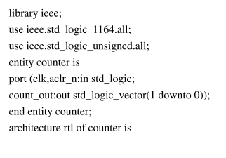
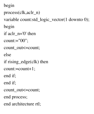
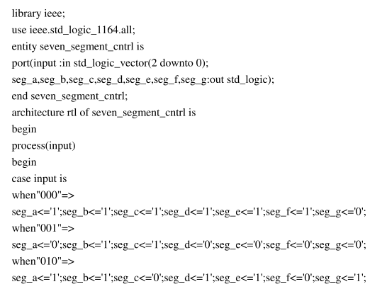
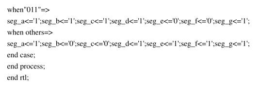
Code for Counter: Code for Seven Segment Control: Use Quartus This design will require you to design your own FSM-Finite State Machine, we learned about
Code for Counter:
Code for Seven Segment Control:
Use Quartus
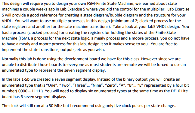
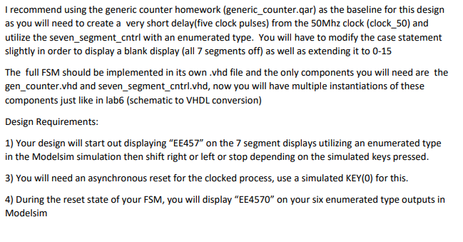
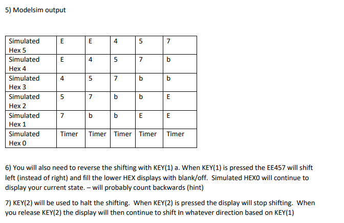
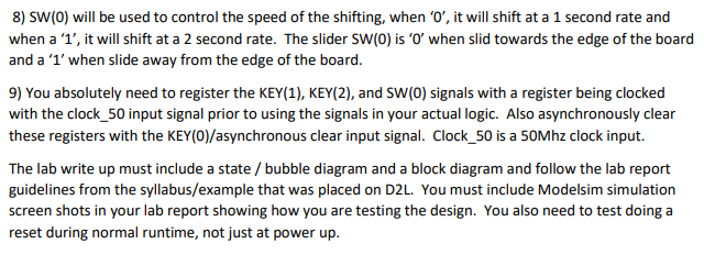
This design will require you to design your own FSM-Finite State Machine, we learned about state machines a couple weeks ago in Lab Exercise 5 where you did the control for the multiplier. Lab Exercise 5 will provide a good reference for creating a state diagram/bubble diagram and the structure for your VHDL. You will want to use multiple processes in this design (minimum of 2; clocked process for the state registers and another for the sate machine transitions). Take a look at your labs VHDL design. You had a process (clocked process) for creating the registers for holding the states of the Finite State Machine (FSM), a process for the next state logic, a mealy process and a moore process, you do not have to have a mealy and moore process for this lab, design it so it makes sense to you. You are free to implement the state transitions, outputs, etc as you wish. Normally this lab is done using the development board we have for this class. However since we are unable to distribute those boards to everyone as most students are remote we will be forced to use an enumerated type to represent the seven segment display. In the labs 1-5b we created a seven segment display. Instead of the binary output you will create an enumerated type that is "One", "Two", "Three... Nine", "Zero", "A", "B"... "E" represented by a four bit number( 0000 - 1111). You will need to display six enumerated types at the same time as the DE 10 Lite board has 6 seven segment displays The clock will still run at a 50 Mhz but I recommend using only five clock pulses per state change.. I recommend using the generic counter homework (generic_counter.qar) as the baseline for this design as you will need to create a very short delay(five clock pulses) from the 50Mhz clock (clock_50) and utilize the seven_segment_cntrl with an enumerated type. You will have to modify the case statement slightly in order to display a blank display (all 7 segments off) as well as extending it to 0-15 The full FSM should be implemented in its own .vhd file and the only components you will need are the gen_counter.vhd and seven_segment_cntrl.vhd, now you will have multiple instantiations of these components just like in lab6 (schematic to VHDL conversion) Design Requirements: 1) Your design will start out displaying "EE457" on the 7 segment displays utilizing an enumerated type in the Modelsim simulation then shift right or left or stop depending on the simulated keys pressed. 3) You will need an asynchronous reset for the clocked process, use a simulated KEY(0) for this. 4) During the reset state of your FSM, you will display "EE4570" on your six enumerated type outputs in Modelsim 5) Modelsim output E E 4 5 7 E 4 5 7 b 4 5 7 b b Simulated Hex 5 Simulated Hex 4 Simulated Hex 3 Simulated Hex 2 Simulated Hex 1 Simulated Hex 0 5 7 b b E 7 b b E E Timer Timer Timer Timer Timer 6) You will also need to reverse the shifting with KEY(1) a. When KEY(1) is pressed the EE457 will shift left (instead of right) and fill the lower HEX displays with blank/off. Simulated HEXO will continue to display your current state. - will probably count backwards (hint) 7) KEY(2) will be used to halt the shifting. When KEY(2) is pressed the display will stop shifting. When you release KEY(2) the display will then continue to shift in whatever direction based on KEY(1) 8) Sw(0) will be used to control the speed of the shifting, when 'o', it will shift at a 1 second rate and when a '1', it will shift at a 2 second rate. The slider SW(0) is 'O' when slid towards the edge of the board and a 'l' when slide away from the edge of the board. 9) You absolutely need to register the KEY(1), KEY(2), and SW(0) signals with a register being clocked with the clock_50 input signal prior to using the signals in your actual logic. Also asynchronously clear these registers with the KEY(O)/asynchronous clear input signal. Clock_50 is a 50Mhz clock input. The lab write up must include a state / bubble diagram and a block diagram and follow the lab report guidelines from the syllabus/example that was placed on D2L. You must include Modelsim simulation screen shots in your lab report showing how you are testing the design. You also need to test doing a reset during normal runtime, not just at power up. library ieee; use ieee.std_logic_1164.all; use ieee.std_logic_unsigned.all; entity counter is port (clk,aclr_n:in std_logic; count_out:out std_logic_vector(1 downto 0)); end entity counter; architecture rtl of counter is begin process(clk, aclr_n) variable count:std_logic_vector(1 downto 0); begin if aclr_n='0' then count:="00"; count_out seg_a seg_a seg_a seg_a seg_a seg_a seg_a seg_a seg_a seg_aStep by Step Solution
There are 3 Steps involved in it
Step: 1

Get Instant Access to Expert-Tailored Solutions
See step-by-step solutions with expert insights and AI powered tools for academic success
Step: 2

Step: 3

Ace Your Homework with AI
Get the answers you need in no time with our AI-driven, step-by-step assistance
Get Started


