Question
// Code from FPGA prototyping by SystemVerilog examples by P. Chu // Implements a 4-bit sign-and-magnitude adder module sign_mag_add #(parameter N=4) ( input logic [N-1:0]

// Code from "FPGA prototyping by SystemVerilog examples" by P. Chu // Implements a 4-bit sign-and-magnitude adder module sign_mag_add #(parameter N=4) ( input logic [N-1:0] a, b, output logic [N-1:0] sum );
// signal declaration logic [N-2:0] mag_a, mag_b, mag_sum, max, min; logic sign_a, sign_b, sign_sum;
// body always_comb begin // separate magnitude and sign mag_a = a[N-2:0]; mag_b = b[N-2:0]; sign_a = a[N-1]; sign_b = b[N-1]; // sort according to magnitude if (mag_a > mag_b) begin max = mag_a; min = mag_b; sign_sum = sign_a; end else begin max = mag_b; min = mag_a; sign_sum = sign_b; end // add/sub magnitude if (sign_a==sign_b) mag_sum = max + min; else mag_sum = max - min; // form output sum = {sign_sum, mag_sum}; end // always_comb endmodule
/* sync_rom is an example module that implements a read-only * memory (ROM) whose data is loaded from a file using the * $readmem system task. Currently takes in a 1-bit clk signal * along with a 4-bit addr to select from its 16 addresses. * The output data is 7 bits wide. */ module sync_rom (input logic clk, input logic [3:0] addr, output logic [6:0] data); // signal declaration logic [6:0] rom [0:15]; // load binary values from a dummy text file into ROM initial $readmemb("data.txt", rom); // synchronously reads out data from requested addr always_ff @(posedge clk) data
// TruthTable
0 1 2 3 4 5 6 7 8 9 A B C D E F 1 2 3 4 5 6 7 0 1 8 9 A B C D E 2 3 4 5 6 7 0 1 2 1 8 9 A B C D 3 4 5 6 7 0 1 2 3 2 1 8 9 A B C 4 5 6 7 0 1 2 3 4 3 2 1 8 9 A B 5 6 7 0 1 2 3 4 5 4 3 2 1 8 9 A 6 7 0 1 2 3 4 5 6 5 4 3 2 1 8 9 7 0 1 2 3 4 5 6 7 6 5 4 3 2 1 8 0 1 2 3 4 5 6 7 8 9 A B C D E F 9 0 1 2 3 4 5 6 9 A B C D E F 8 A 9 0 1 2 3 4 5 A B C D E F 8 9 B A 9 0 1 2 3 4 B C D E F 8 9 A C B A 9 0 1 2 3 C D E F 8 9 A B D C B A 9 0 1 2 D E F 8 9 A B C E D C B A 9 0 1 E F 8 9 A B C D F E D C B A 9 0 F 8 9 A B C D E
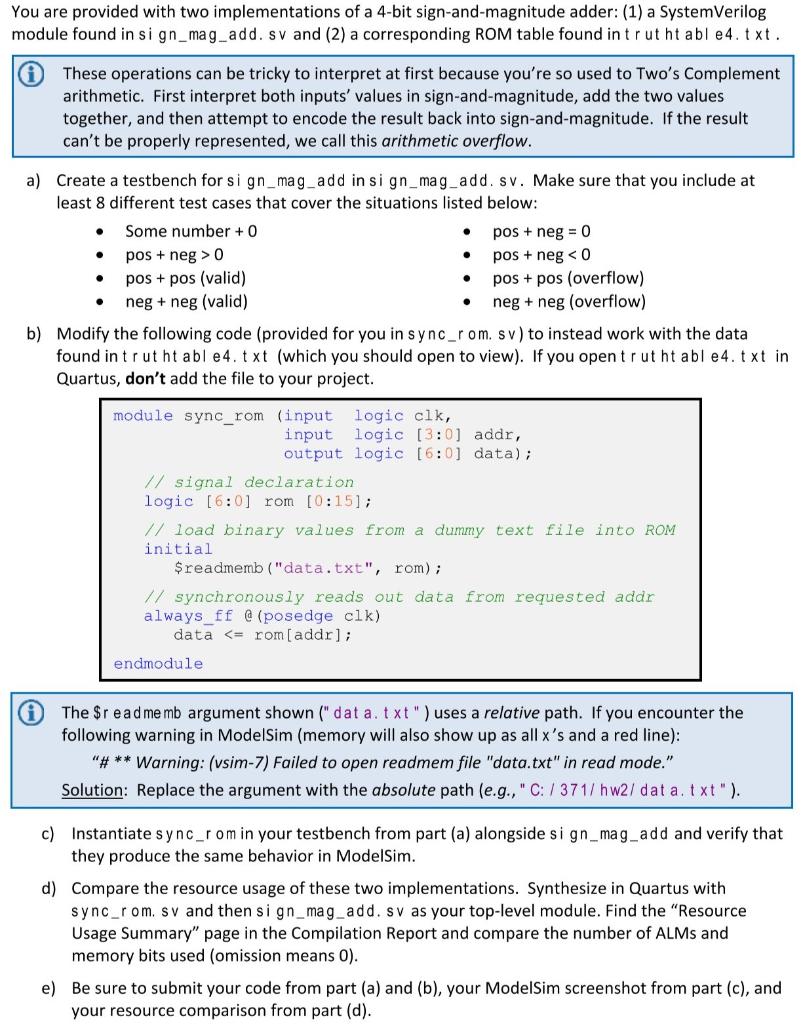
You are provided with two implementations of a 4-bit sign-and-magnitude adder: (1) a SystemVerilog module found in sign_mag_add. sv and (2) a corresponding ROM table found in trutht able4.txt. These operations can be tricky to interpret at first because you're so used to Two's Complement arithmetic. First interpret both inputs' values in sign-and-magnitude, add the two values together, and then attempt to encode the result back into sign-and-magnitude. If the result can't be properly represented, we call this arithmetic overflow. . . . a) Create a testbench for sign_mag_add in sign_mag_add. sv. Make sure that you include at least 8 different test cases that cover the situations listed below: Some number + 0 pos + neg = 0 pos + neg > 0 pos + neg 0 pos + negStep by Step Solution
There are 3 Steps involved in it
Step: 1

Get Instant Access to Expert-Tailored Solutions
See step-by-step solutions with expert insights and AI powered tools for academic success
Step: 2

Step: 3

Ace Your Homework with AI
Get the answers you need in no time with our AI-driven, step-by-step assistance
Get Started


