

Question
Code to modify #define trigPin1 13 // Trig for sensor 1 #define echoPin1 12 // Echo for sensor 1 #define trigPin2 11 // Trig for
Code to modify
#define trigPin1 13 // Trig for sensor 1 #define echoPin1 12 // Echo for sensor 1 #define trigPin2 11 // Trig for sensor 2 #define echoPin2 10 // Echo for sensor 2
float duration, distance, duration1, distance1, duration2, distance2; void setup() { Serial.begin (9600); //Serial communications at 9600 bps pinMode(trigPin1, OUTPUT); //Set the trigPin1 as output pinMode(echoPin1, INPUT); //Set the echoPin1 as input pinMode(trigPin2, OUTPUT); //Set the trigPin2 as output pinMode(echoPin2, INPUT); //Set the echoPin2 as input }
void loop() {
FindRange(trigPin1, echoPin1); duration1 = duration; distance1 = distance; FindRange(trigPin2, echoPin2); duration2 = duration; distance2 = distance; Serial.print(distance1); Serial.print(" cm "); Serial.print(distance2); Serial.println(" cm"); delay(100); }
void FindRange(int trigPin, int echoPin) { //Trigger the sensor by sending a HIGH pulse of 10 microseconds. But, before that, give a short LOW pulse to ensure youll get a clean HIGH pulse digitalWrite(trigPin, LOW); // Send out a Low trigger delayMicroseconds(2); // Wait 2 ms digitalWrite(trigPin, HIGH); // Send out a High trigger delayMicroseconds(10); // Wait 10 ms digitalWrite(trigPin, LOW); //Send out a Low trigger. duration = pulseIn(echoPin, HIGH); //Read the HIGH pulse whose duration is the time (in microseconds) from the sending of the ping to the reception of its echo off of an object. distance = (duration / 2) * 0.03435; //Sound speed = 0.03435cm/ct }
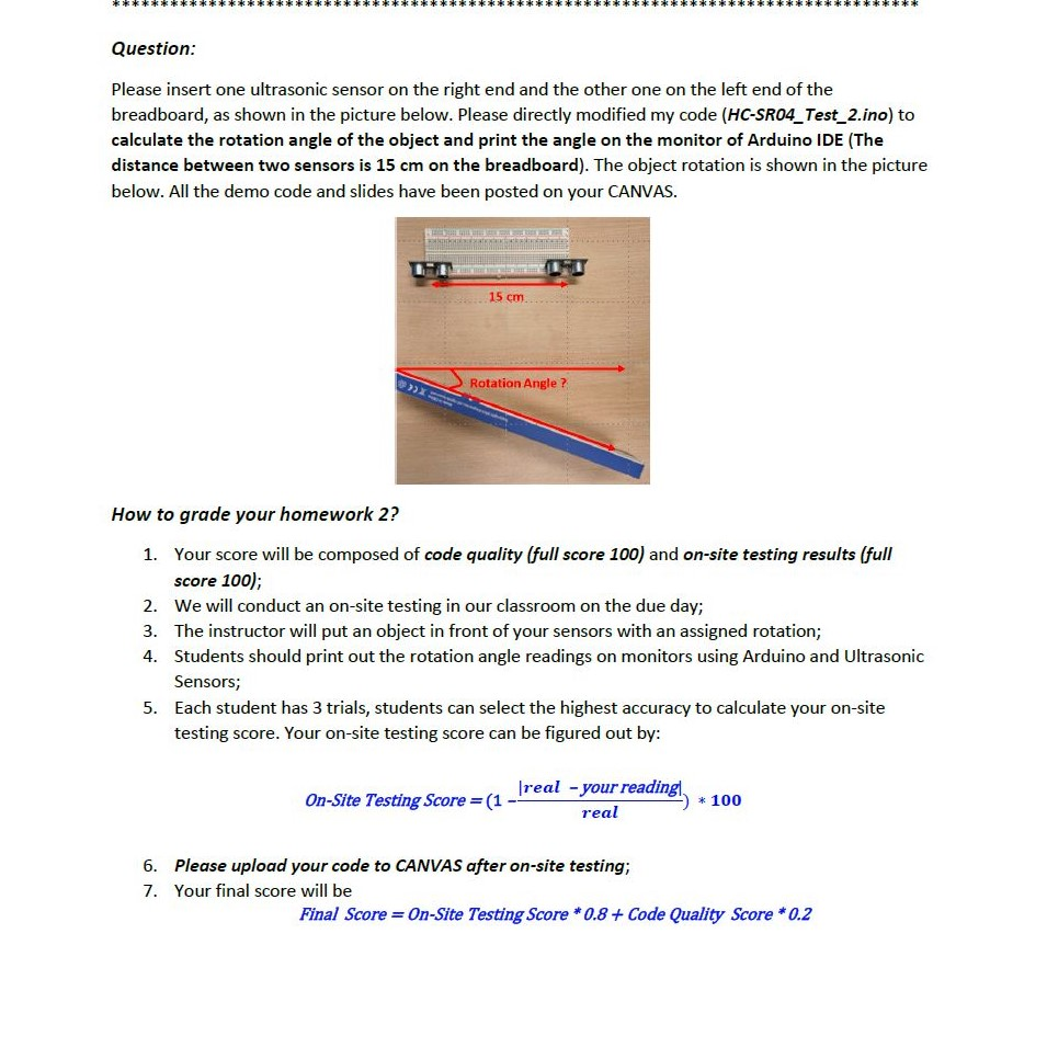
** **** *** *** ***** * **** ****** * ***** ******* ********* ***** **** ** ** ****** * *** * ******* ********* ** **** **** ** Question: Please insert one ultrasonic sensor on the right end and the other one on the left end of the breadboard, as shown in the picture below. Please directly modified my code (HC-SR04_Test_2.ino) to calculate the rotation angle of the object and print the angle on the monitor of Arduino IDE (The distance between two sensors is 15 cm on the breadboard). The object rotation is shown in the picture below. All the demo code and slides have been posted on your CANVAS. 15 cm Rotation Angle? How to grade your homework 2? 1. Your score will be composed of code quality (full score 100) and on-site testing results (full score 100); 2. We will conduct an on-site testing in our classroom on the due day; 3. The instructor will put an object in front of your sensors with an assigned rotation; 4. Students should print out the rotation angle readings on monitors using Arduino and Ultrasonic Sensors; 5. Each student has 3 trials, students can select the highest accuracy to calculate your on-site testing score. Your on-site testing score can be figured out by: real - your reading On-Site Testing Score =(1 - real 6. Please upload your code to CANVAS after on-site testing; 7. Your final score will be Final Score = On-Site Testing Score * 0.8 + Code Quality Score * 0.2 ** **** *** *** ***** * **** ****** * ***** ******* ********* ***** **** ** ** ****** * *** * ******* ********* ** **** **** ** Question: Please insert one ultrasonic sensor on the right end and the other one on the left end of the breadboard, as shown in the picture below. Please directly modified my code (HC-SR04_Test_2.ino) to calculate the rotation angle of the object and print the angle on the monitor of Arduino IDE (The distance between two sensors is 15 cm on the breadboard). The object rotation is shown in the picture below. All the demo code and slides have been posted on your CANVAS. 15 cm Rotation Angle? How to grade your homework 2? 1. Your score will be composed of code quality (full score 100) and on-site testing results (full score 100); 2. We will conduct an on-site testing in our classroom on the due day; 3. The instructor will put an object in front of your sensors with an assigned rotation; 4. Students should print out the rotation angle readings on monitors using Arduino and Ultrasonic Sensors; 5. Each student has 3 trials, students can select the highest accuracy to calculate your on-site testing score. Your on-site testing score can be figured out by: real - your reading On-Site Testing Score =(1 - real 6. Please upload your code to CANVAS after on-site testing; 7. Your final score will be Final Score = On-Site Testing Score * 0.8 + Code Quality Score * 0.2Step by Step Solution
There are 3 Steps involved in it
Step: 1

Get Instant Access to Expert-Tailored Solutions
See step-by-step solutions with expert insights and AI powered tools for academic success
Step: 2

Step: 3
Ace Your Homework with AI
Get the answers you need in no time with our AI-driven, step-by-step assistance
Get Started
Advances In Database Technology Edbt 94 4th International Conference On Extending Database Technology Cambridge United Kingdom March 1994 Proceedings Lncs 779
Authors: Matthias Jarke ,Janis Bubenko ,Keith Jeffery
1994th Edition
3540578188, 978-3540578185