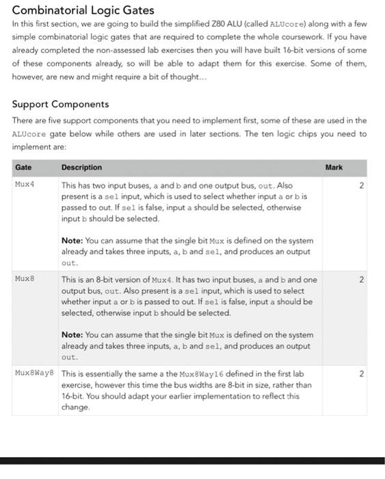
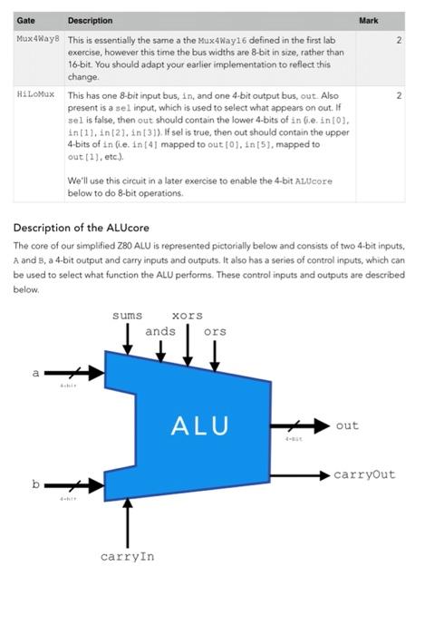
Combinatorial Logic Gates In this first section, we are going to build the simplified Z80 ALU (called ALUcore) along with a few simple combinatorial logic gates that are required to complete the whole coursework. If you have already completed the non-assessed lab exercises then you will have built 16-bit versions of some of these components already, so will be able to adapt them for this exercise. Some of them, however, are new and might require a bit of thought... Gate Mark Support Components There are five support components that you need to implement first, some of these are used in the ALUcore gate below while others are used in later sections. The ten logic chips you need to implement are: Description Mux 4 This has two input buses, a and b and one output bus, out. Also present is a sel input, which is used to select whether input a orbis passed to out. If sel is false, input a should be selected, otherwise input b should be selected Note: You can assume that the single bit Mux is defined on the system already and takes three inputs, a, b and sel, and produces an output 2 out. Mux 2 This is an 8-bit version of Muxt. It has two input buses, a and b and one output bus, out. Also present is a sel input, which is used to select whether input a orb is passed to out. If sel is false, input a should be selected, otherwise input b should be selected. Note: You can assume that the single bit Mux is defined on the system already and takes three inputs, a, b and sel, and produces an output out. MuxWays This is essentially the same a the Mux8Way16 defined in the first lab exercise, however this time the bus widths are 8-bit in size, rather than 16-bit . You should adapt your earlier implementation to reflect this change 2 Gate Mark 2 2 Description Mux4way8 This is essentially the same a the MuxtWay16 defined in the first lab exercise, however this time the bus widths are 8-bit in size, rather than 16-bit . You should adapt your earlier implementation to reflect this change HiLoMX This has one 8-bit input bus, in, and one 4-bit output bus, out. Also present is a sel input, which is used to select what appears on out. If sel is false, then out should contain the lower 4-bits of inle, into), in 11. in 21. in 31). If sel is true, then out should contain the upper 4-bits of in die. In [4] mapped to out 101. in 5), mapped to out 1), etc.). We'll use this circuit in a later exercise to enable the 4-bit Alucore below to do 8-bit operations. Description of the ALUcore The core of our simplified Z80 ALU is represented pictorially below and consists of two 4-bit inputs, A and B, a 4-bit output and carry inputs and outputs. It also has a series of control inputs, which can be used to select what function the ALU performs. These control inputs and outputs are described below sums xors ors ands a ALU out carryout b carryin As the diagram above shows, the Alucore has two 4-bit inputs (a and b), one carryin input, and four control signals and produces a 4-bit output (out) and a carry output. The inputs and output are multi-bit, and so we represent them in the HDL as buses. A bus is just a collection of logic signals that we keep together in this case they reach represent a numeric value in binary). We can define them in the HDL by suffixing the pin name with square brackets, thus: a[4]. This denotes that a is a bus 4-bits wide, numbered 0-3. Each individual bit can be accessed by placing the number of the required bit in the square brackets. So a [3] would access the fourth bit (remember, numbering starts from zero!) from the right. Again, re-read Appendix A of nandatetris for more details on the HDL syntax. The four control signals, sums, ands, xors, and ors, are used to control the output produced by the ALU by selecting between the output of the four possible functions it can perform. These are used to select whether the two inputs are Add-ed, And-ed, XOR-ed, or OR-ed together respectively - each of these can be produced using the components supplied. You can assume that only one control signal will be active at a time, and so the order you select between the possible outputs doesn't matter. The carryin input of the ALUcore should be connected to the carryin of your Add 4, while the carryout signal of the ALUcoure should be connected to the carryout of your Add4 when adds is true, otherwise it should be false. This completes the implementation of our ALU's core - in the final section, you will build some more logic to drive the core, enabling it to perform subtraction as well as addition, and also to be able to perform 8-bit operations