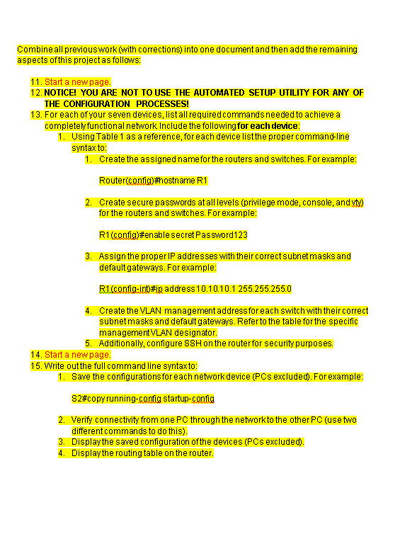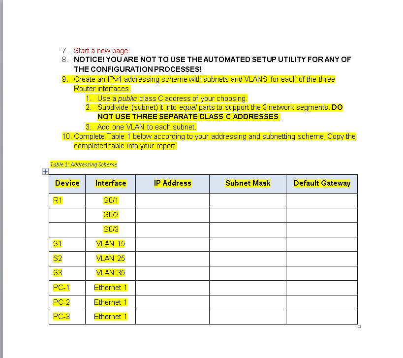

Combine all previouswork (with corrections) into one document and then add the remaining aspects ofthis project as follows: 11. Start a newpage 12. NOTICE! YOU ARE NOT TO USE THE AUTOMATED SETUP UTILITY FOR ANY OF THE CONFIGURATION PROCESSES! 13. For each of your seven devices, list all requiredcommands needed to achieve a completey functional network Include the following for each device 1. Using Table 1 as a reference, for each device listthe proper command-line syntax to Create the assigned name for the routers and switches. For example: Router(config)#h0stname RI 2. Create secure passwords at all levels (privilege mode, console, and vt) for the routers and switches. For example: R1 (config)#en able secret Password! 23 3. Assign the proper IP addresses with their correct subnet masks and default gateways. For example: R1(config-int)# Raddress 10.10.10.1255 255255.0 Create the VLAN management addressfor each switch with their correct subnet masks and default gateways. Refer to the table for the specific management VLAN designator. Additionally, configure SSH on the router for security purposes. 5. 14. Start a new page. 15. Write outthe full command line syntax to: 1. Save the configurations for each network device (PCs excluded). For example S2#copy running-config startup-config 2. Verify connectivity from one PC through the network to the other PC (use two different commands to do this). Display the saved configuration ofthe devices (PCs excluded). Display the routing table on the router. 3. 4. 7. Start a new page 8. NOTICE! YOU ARE NOT TO USE THE AUTOMATED SETUP UTILITY FORANY OF THE CONFIGURATION PROCESSES! 9. Create an IPv4 addressing scheme with subnets and VLANS for each of the three Router interfaces. 1. Use a public class C address of your choosing. Subdivide (subnet) it into equal parts to support the 3 network segments. Do NOT USE THREE SEPARATE CLASS C ADDRESSES. 2. 3. Add one VLAN to each subnet 10. Complete Table 1 below according to your addressing and subnetting scheme. Copy the completed table into your report. Table 1: Addressing Scheme Device Interface IP Address Subnet Mask Default Gateway R1 G0/1 GO/2 GO/3 VLAN 15 VLAN 25 VLAN 35 S1 S2 S3 PC-1 Ethernet 1 PC-2 PC-3 Ethernet 1 Ethernet 1 Combine all previouswork (with corrections) into one document and then add the remaining aspects ofthis project as follows: 11. Start a newpage 12. NOTICE! YOU ARE NOT TO USE THE AUTOMATED SETUP UTILITY FOR ANY OF THE CONFIGURATION PROCESSES! 13. For each of your seven devices, list all requiredcommands needed to achieve a completey functional network Include the following for each device 1. Using Table 1 as a reference, for each device listthe proper command-line syntax to Create the assigned name for the routers and switches. For example: Router(config)#h0stname RI 2. Create secure passwords at all levels (privilege mode, console, and vt) for the routers and switches. For example: R1 (config)#en able secret Password! 23 3. Assign the proper IP addresses with their correct subnet masks and default gateways. For example: R1(config-int)# Raddress 10.10.10.1255 255255.0 Create the VLAN management addressfor each switch with their correct subnet masks and default gateways. Refer to the table for the specific management VLAN designator. Additionally, configure SSH on the router for security purposes. 5. 14. Start a new page. 15. Write outthe full command line syntax to: 1. Save the configurations for each network device (PCs excluded). For example S2#copy running-config startup-config 2. Verify connectivity from one PC through the network to the other PC (use two different commands to do this). Display the saved configuration ofthe devices (PCs excluded). Display the routing table on the router. 3. 4. 7. Start a new page 8. NOTICE! YOU ARE NOT TO USE THE AUTOMATED SETUP UTILITY FORANY OF THE CONFIGURATION PROCESSES! 9. Create an IPv4 addressing scheme with subnets and VLANS for each of the three Router interfaces. 1. Use a public class C address of your choosing. Subdivide (subnet) it into equal parts to support the 3 network segments. Do NOT USE THREE SEPARATE CLASS C ADDRESSES. 2. 3. Add one VLAN to each subnet 10. Complete Table 1 below according to your addressing and subnetting scheme. Copy the completed table into your report. Table 1: Addressing Scheme Device Interface IP Address Subnet Mask Default Gateway R1 G0/1 GO/2 GO/3 VLAN 15 VLAN 25 VLAN 35 S1 S2 S3 PC-1 Ethernet 1 PC-2 PC-3 Ethernet 1 Ethernet 1


