

Question: COMP2340 Lab #4 - Micro-instructions Sem 2, 2020/2021 EXERCISE: Exploration with Simple Micro-instructions This lab explores the commands required to instruct a data path consisting
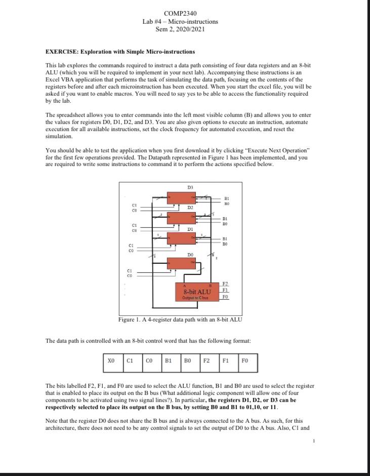
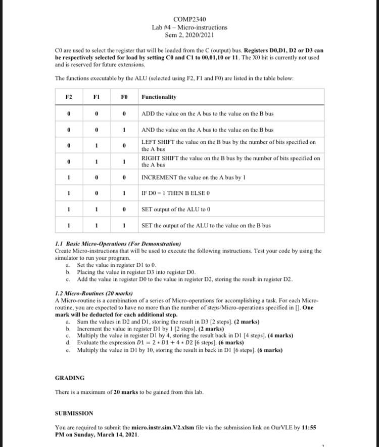
COMP2340 Lab #4 - Micro-instructions Sem 2, 2020/2021 EXERCISE: Exploration with Simple Micro-instructions This lab explores the commands required to instruct a data path consisting of four data registers and an 8-bit ALU (which you will be required to implement in your next lab). Accompanying these instructions is an Excel VBA application that performs the task of simulating the data path, focusing on the contents of the registers before and after each microinstruction has been executed. When you start the excel file, you will be asked if you want to enable macros. You will need to say yes to be able to access the functionality required by the lab. The spreadsheet allows you to enter commands into the left most visible column (B) and allows you to enter the values for registers DO, DI, D2, and D3. You are also given options to execute an instruction, automate execution for all available instructions, set the clock frequency for automated execution, and reset the simulation. You should be able to test the application when you first download it by clicking "Execute Next Operation for the first few operations provided. The Datapath represented in Figure I has been implemented, and you are required to write some instructions to command it to perform the actions specified below. D3 B1 BO CI 00 D2 B1 DO C: CO DI BI DO C1 CO DO CI 8-bit ALU Output to Chus FZ F1 FO Figure 1. A 4-register data path with an 8-bit ALU The data path is controlled with an 8-bit control word that has the following format: | co | 1 | F2F1FO The bits labelled F2, F1, and FO are used to select the ALU function, Bl and BO are used to select the register that is enabled to place its output on the B bus (What additional logic component will allow one of four components to be activated using two signal lines?). In particular, the registers D1, D2, or D3 can be respectively selected to place its output on the B bus, by setting Bo and B1 to 01.10, or 11. Note that the register Do does not share the B bus and is always connected to the A bus. As such, for this architecture, there does not need to be any control signals to set the output of Do to the A bus. Also, Cl and COMP2340 Lab #4 - Micro-instructions Sem 2, 2020/2021 CO are used to select the register that will be loaded from the C (output) bus. Registers DOD1, D2 or D3 can be respectively selected for load by setting CO and CI to 00,01,10 or 11. The XO bit is currently not used and is reserved for future extensions. The functions executable by the ALU (selected using F2, F1 and FO) are listed in the table below: F2 FI FO Functionality ADD the value on the A bus to the value on the Bbus 0 0 0 0 0 1 0 1 0 0 1 1 AND the value on the A bus to the value on the B bus LEFT SHIFT the value on the B bus by the number of bits specified on the A bus RIGHT SHIFT the value on the B bus by the number of bits specified on the A bus INCREMENT the value on the A bus by 1 IF DO -1 THEN B ELSE O 1 0 0 1 0 1 1 0 SET output of the ALU to 0 1 1 1 SET the output of the ALU to the value on the B bus 1.1 Basic Micro-Operations (For Demonstration) Create Micro-instructions that will be used to execute the following instructions. Test your code by using the simulator to run your program, a. Set the value in register Dl to 0. b. Placing the value in register D3 into register Do. c. Add the value in register Do to the value in register D2, storing the result in register D2. 1.2 Micro-Routines (20 marks) A Micro-routine is a combination of a series of Micro-operations for accomplishing a task. For each Micro- routine, you are expected to have no more than the number of steps/Micro-operations specified in []. One mark will be deducted for each additional step. a. Sum the values in D2 and Di, storing the result in D3 (2 steps). (2 marks) b. Increment the value in register DI by 1 (2 steps). (2 marks) c. Multiply the value in register DI by 4, storing the result back in D1 [4 steps). (4 marks) d. Evaluate the expression D1 = 2.01 +4 + D2 [6 steps). (6 marks) e. Multiply the value in D1 by 10, storing the result in back in DI [6 steps). (6 marks) GRADING There is a maximum of 20 marks to be gained from this lab. SUBMISSION You are required to submit the micro.instr.sim.V2.xlsm file via the submission link on Our VLE by 11:55 PM on Sunday, March 14, 2021. COMP2340 Lab #4 - Micro-instructions Sem 2, 2020/2021 EXERCISE: Exploration with Simple Micro-instructions This lab explores the commands required to instruct a data path consisting of four data registers and an 8-bit ALU (which you will be required to implement in your next lab). Accompanying these instructions is an Excel VBA application that performs the task of simulating the data path, focusing on the contents of the registers before and after each microinstruction has been executed. When you start the excel file, you will be asked if you want to enable macros. You will need to say yes to be able to access the functionality required by the lab. The spreadsheet allows you to enter commands into the left most visible column (B) and allows you to enter the values for registers DO, DI, D2, and D3. You are also given options to execute an instruction, automate execution for all available instructions, set the clock frequency for automated execution, and reset the simulation. You should be able to test the application when you first download it by clicking "Execute Next Operation for the first few operations provided. The Datapath represented in Figure I has been implemented, and you are required to write some instructions to command it to perform the actions specified below. D3 B1 BO CI 00 D2 B1 DO C: CO DI BI DO C1 CO DO CI 8-bit ALU Output to Chus FZ F1 FO Figure 1. A 4-register data path with an 8-bit ALU The data path is controlled with an 8-bit control word that has the following format: | co | 1 | F2F1FO The bits labelled F2, F1, and FO are used to select the ALU function, Bl and BO are used to select the register that is enabled to place its output on the B bus (What additional logic component will allow one of four components to be activated using two signal lines?). In particular, the registers D1, D2, or D3 can be respectively selected to place its output on the B bus, by setting Bo and B1 to 01.10, or 11. Note that the register Do does not share the B bus and is always connected to the A bus. As such, for this architecture, there does not need to be any control signals to set the output of Do to the A bus. Also, Cl and COMP2340 Lab #4 - Micro-instructions Sem 2, 2020/2021 CO are used to select the register that will be loaded from the C (output) bus. Registers DOD1, D2 or D3 can be respectively selected for load by setting CO and CI to 00,01,10 or 11. The XO bit is currently not used and is reserved for future extensions. The functions executable by the ALU (selected using F2, F1 and FO) are listed in the table below: F2 FI FO Functionality ADD the value on the A bus to the value on the Bbus 0 0 0 0 0 1 0 1 0 0 1 1 AND the value on the A bus to the value on the B bus LEFT SHIFT the value on the B bus by the number of bits specified on the A bus RIGHT SHIFT the value on the B bus by the number of bits specified on the A bus INCREMENT the value on the A bus by 1 IF DO -1 THEN B ELSE O 1 0 0 1 0 1 1 0 SET output of the ALU to 0 1 1 1 SET the output of the ALU to the value on the B bus 1.1 Basic Micro-Operations (For Demonstration) Create Micro-instructions that will be used to execute the following instructions. Test your code by using the simulator to run your program, a. Set the value in register Dl to 0. b. Placing the value in register D3 into register Do. c. Add the value in register Do to the value in register D2, storing the result in register D2. 1.2 Micro-Routines (20 marks) A Micro-routine is a combination of a series of Micro-operations for accomplishing a task. For each Micro- routine, you are expected to have no more than the number of steps/Micro-operations specified in []. One mark will be deducted for each additional step. a. Sum the values in D2 and Di, storing the result in D3 (2 steps). (2 marks) b. Increment the value in register DI by 1 (2 steps). (2 marks) c. Multiply the value in register DI by 4, storing the result back in D1 [4 steps). (4 marks) d. Evaluate the expression D1 = 2.01 +4 + D2 [6 steps). (6 marks) e. Multiply the value in D1 by 10, storing the result in back in DI [6 steps). (6 marks) GRADING There is a maximum of 20 marks to be gained from this lab. SUBMISSION You are required to submit the micro.instr.sim.V2.xlsm file via the submission link on Our VLE by 11:55 PM on Sunday, March 14, 2021
Step by Step Solution
There are 3 Steps involved in it

Get step-by-step solutions from verified subject matter experts