Question
Complete the connection of 7-segment 3-character LED display by connecting 2nd and 3rd characters to LPC4088. The lab will consist of two steps: a) In
Complete the connection of 7-segment 3-character LED display by connecting 2nd and 3rd characters to LPC4088.
The lab will consist of two steps: a) In this step you will connect the second character of the 3-characters LED panel. To demonstrate successful completion, the students will display a continuous loop of counting up from 00-FF on the character display. After the loop ends, both the dots should blink in the displays and restart the count up loop again. Example: 00, ..., 0F, 10, ..., 1F,20, ..., 2F, 30, ..., 3F, 40, ..., 4F,50, ..., 5F, ..., ..., A0, AF, ..., b0, bF, ..., C0, CF, ..., ..., F0, ..., FF b) In this step you will connect the third character of the 3-characters LED panel. To demonstrate successful completion, the students will display a continuous loop of counting up from 000-FFF on the character display. Similar to the example above. After the loop ends, all the dots should blink in the displays and restart the count up loop again.
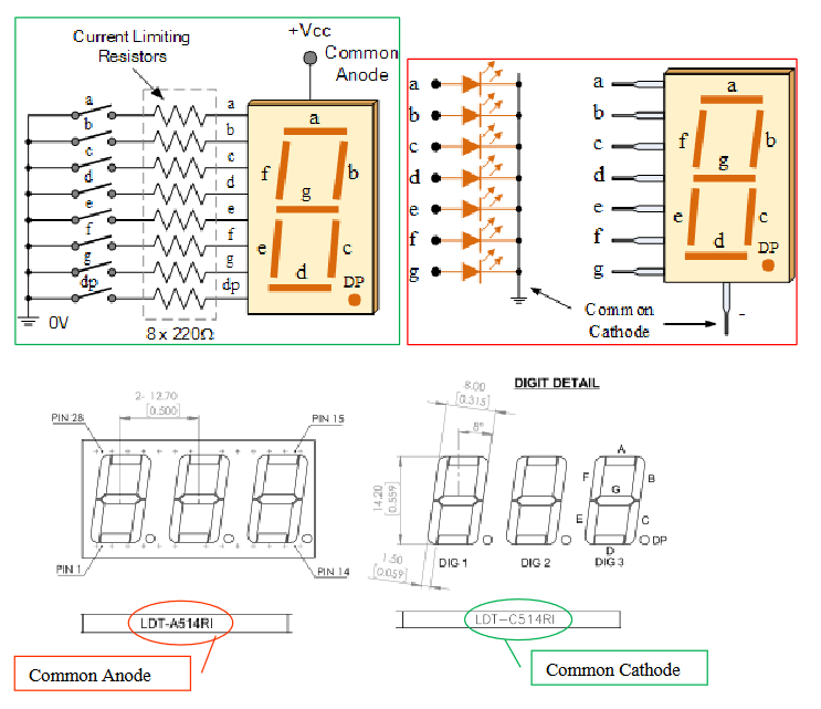
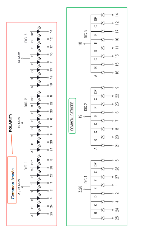
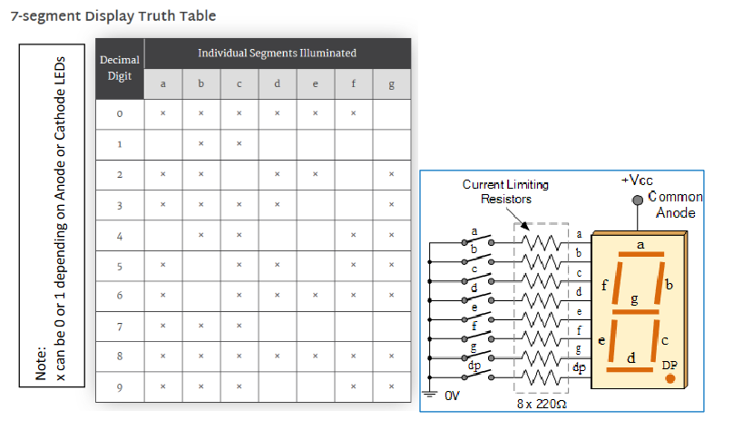
You can directly connect the 3-character 7-segment LEDs to the LPC4088, similar to how you did for the external LED. However, consider this; a single character of a 7-segment display requires 8 pins, 7 for forming the character and 1 for the dot, besides power and ground pins. So, for 3-characters panel we will need 24 pins from the LPC4088 for LEDs. The LPC4088 has only 44 pins, the number of GPIO pins on LPC4088 are even more limited, since some pins are used for power, ground, analog input and output, etc. So as not to use too many pins on the board, we are going to use a serial input/parallel output shift register. The data can be shifted in serial order and the parallel outputs can drive the LEDs.
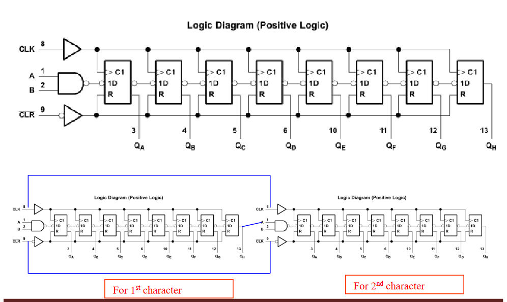
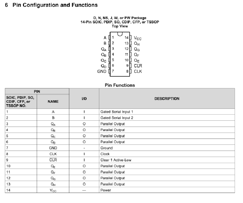
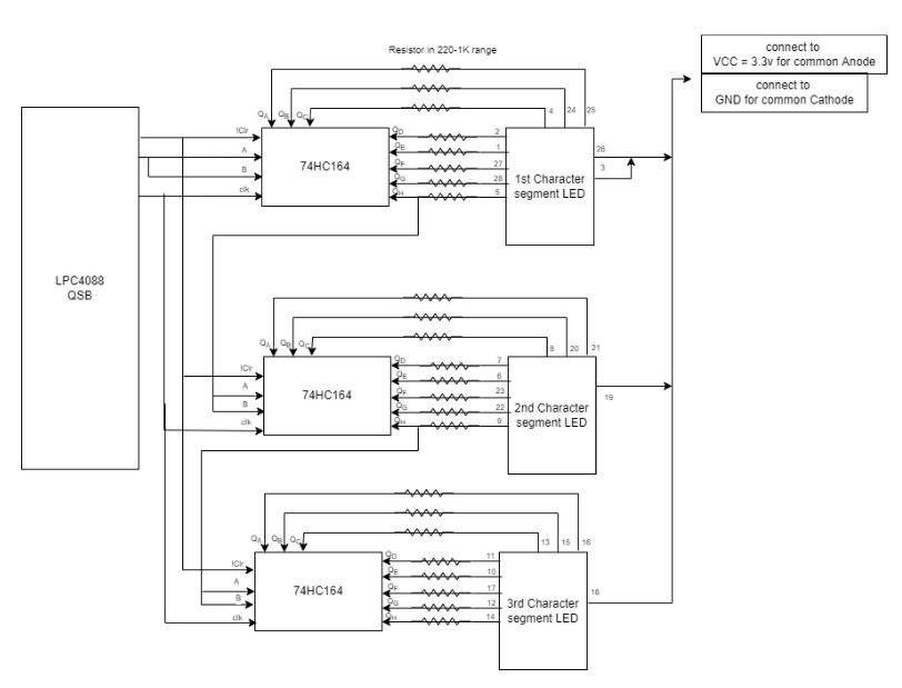
At this point, you should have the first shift-register working to light up the first character display. To add the functionality for next character you will extend the serial interface by adding more 74HC164 chips and serially linking them to the existing 74HC164 chip. The last output, pin QH, of the previous 74HC164, should be the input, pin A of the next 74HC164. The reset (pin !CLR ) and clock (pin CLK) of all the 74HC164s should be connected together, as we want to reset and clock all the shift-registers simultaneously. See the connections in the figure below. Couple of important things: Once you finish this experiment, DO NOT dismantle the circuit. We will reuse it multiple times. Also use the power+ground from the NI Elvis breadboard connection, NOT from the LCP4088QSB, for 7-segment LEDs and 74HC164 chips. The power on the NI Elvis board should be set to 3.3v NOT 5v for the shift register. Use functions in C to drive the LEDs to correct values, as you are going to reuse the circuit and will have to display values.
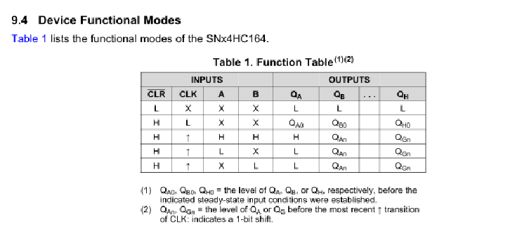
Student have to connect all 3-characters from the 3-character 7-segment LED panel, to the LPC4088QSB and test it. To connect, students are going to use three 74HC164, one for each character of the display. 74HC164 is a serial-in/parallel-out IC. Student should keep the connection short and clean, because there will be a lot of wires between 74HC164 and 7- segment LEDs. Students must use only 3 functional pins connections between LPC4088QSB and 74HC164s. One pin (LPC4088 pin28) to reset the 74HC164s, one pin (LPC4088 pin27) to clock the 74HC164s, and one pin (LPC4088 pin30) for sending the serial data. Besides these functional pins, student will connect power and ground pins for the 7-segment 3-character display and all 74HC164s. Students will write a C program to run the display. Before using the display, students must send a reset pulse. The !CLR pin on 74HC164 is active low so the following sequence will reset it, a 1 followed by a 0 and finally a 1, at the beginning of the program. 74HC164 will not work properly without reset. You have to generate the clock by putting the clock pin in a controlled loop. The data will not be accepted by 74HC164 without the clock being active. The data is accepted by 74HC164 on the rising-edge of the clock only. You have to program in such a manner that your clock and data are synchronized. Make sure you have only one clock-cycle per data bit. To send 8 bits of data you will have to clock eight times sending one bit at a time and so on. The order of sending bits is important, first bit will go to QH after 8 cycles and the last bit will be in QA.
The final goal of the experiment is to be able to count 000-FFF and display it correctly on the 7-segment LED.
Step by Step Solution
There are 3 Steps involved in it
Step: 1

Get Instant Access to Expert-Tailored Solutions
See step-by-step solutions with expert insights and AI powered tools for academic success
Step: 2

Step: 3

Ace Your Homework with AI
Get the answers you need in no time with our AI-driven, step-by-step assistance
Get Started


