 Computer Architecture problem. Textbook pages attached.
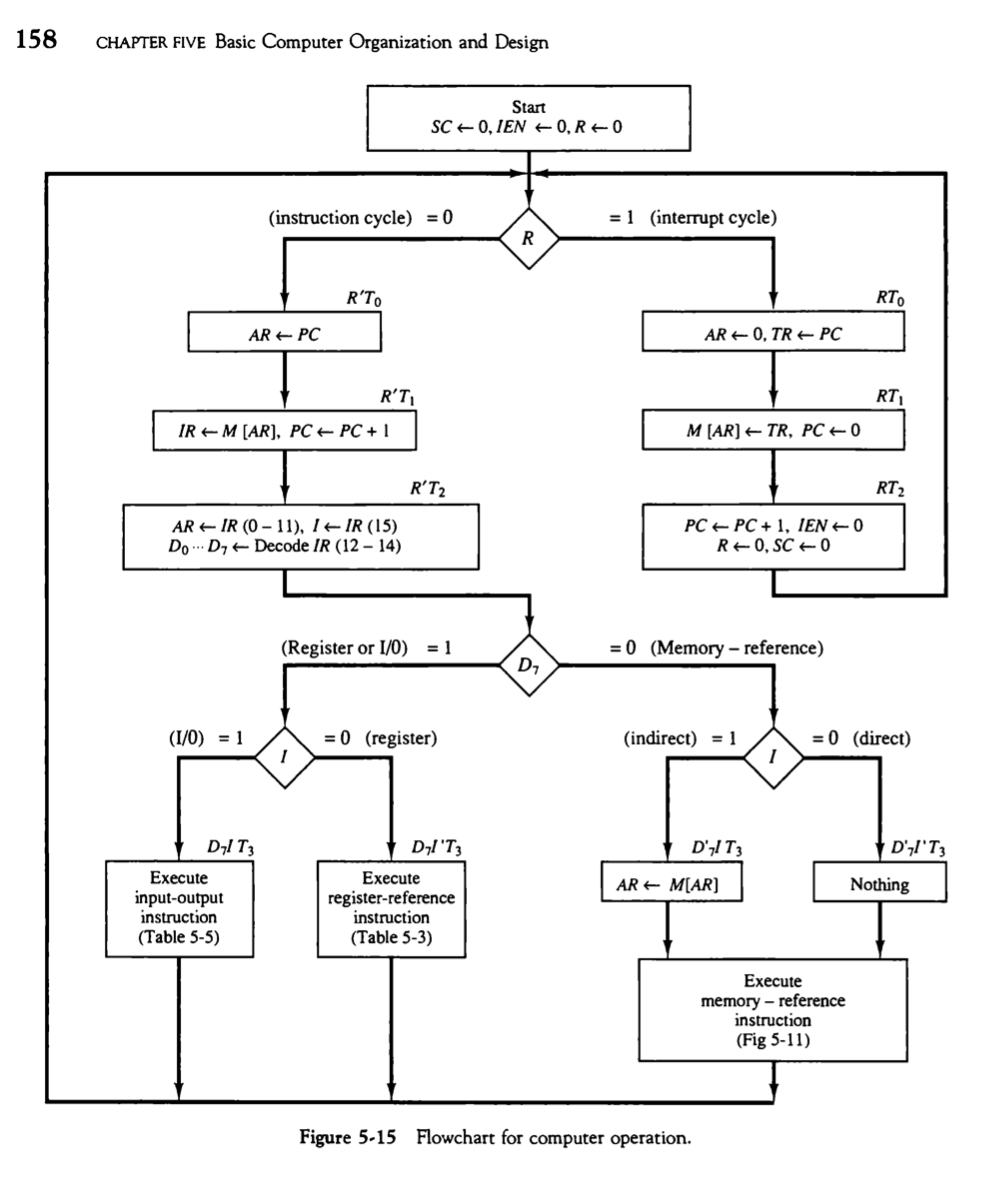
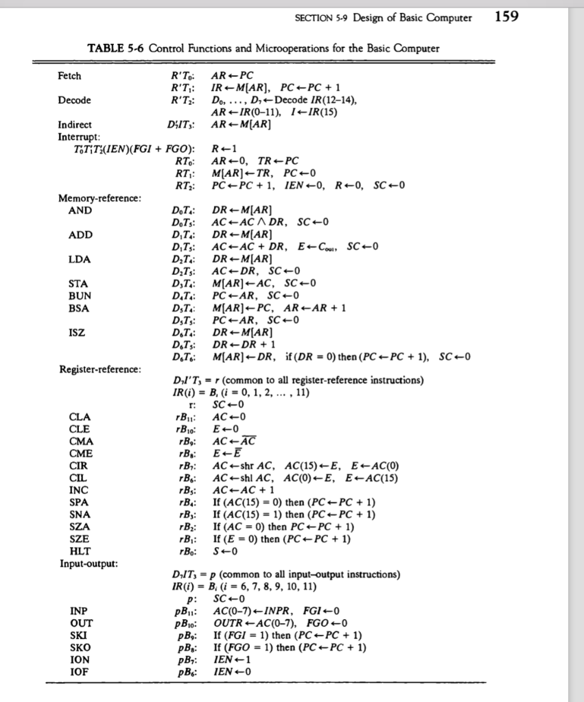
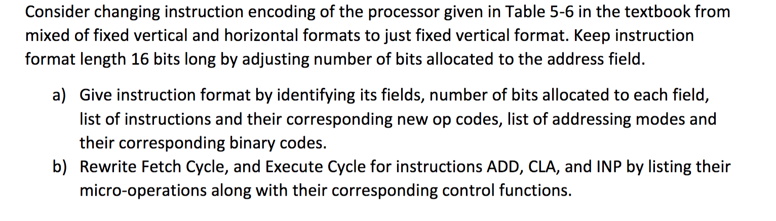
Consider changing instruction encoding of the processor given in Table 5-6 in the textbook from mixed of fixed vertical and horizontal formats to just fixed vertical format. Keep instruction format length 16 bits long by adjusting number of bits allocated to the address field. a) Give instruction format by identifying its fields, number of bits allocated to each field, list of instructions and their corresponding new op codes, list of addressing modes and their corresponding binary codes. b) Rewrite Fetch Cycle, and execute Cycle for instructions ADD, CLA, and INP by listing their micro-operations along with their corresponding control functions. 158 CHAPTER FIVE Basic Computer Organization and Design Start SC + 0,IEN ORO (instruction cycle) = 0 = 1 (interrupt cycle) RT AR + PC AR-0, TRe PC RPT IR + M (AR), PC + PC + 1 M (AR) TR, PC +0 R'T2 AR IR (0 - 11), I IR (15) DOD, Decode IR (12 - 14) PC + PC + 1, IENO REO, SCO (Register or 1/0) = 1 = 0 (Memory - reference) (1/0) = 1 = 0 (register) (indirect) = 1 = 0 (direct) DIT DI'T D' IT3 D',I'T3 AR + MAR] Nothing Execute input-output instruction (Table 5-5) Execute register-reference instruction (Table 5-3) Execute memory-reference instruction (Fig 5-11) Figure 5-15 Flowchart for computer operation. SECTION 5-9 Design of Basic Computer 159 TABLE 5-6 Control Functions and Microoperations for the Basic Computer Fetch R'To: ARPC R'T: IR - MAR), PC - PC + 1 Decode R'Tz: Do, ..., D, Decode IR(12-14), AR-IR(0-11), 1-IR(15) Indirect DIT: ARM[AR] Interrupt: TTT (IEN)(FGI + FGO): R-1 RT: AR-0, TR PC RT: MAR]-TR, PC+0 RT: PC PC + 1, IEN-O, RO, SCO Memory-reference: AND DT: DRM[AR] AC-AC A DR, SC-0 ADD DT: DR M[AR] DTs: ACAC + DR, E-Cow SC-0 LDA DT: DR MAR] DzTs: AC DR, SC-0 STA D,T: M[AR] - AC, SC 0 BUN DT: PC -AR, SC-0 BSA DT: M(AR)- PC, AR-AR + 1 Dsts: PCAR, SCO ISZ D.T: DR MAR] D.Ts: DR DR + 1 D.T.: M(AR) --DR, if(DR = 0) then (PC - PC + 1), SCO Register-reference: DI'T, = r (common to all register-reference instructions) IR(i) = B. (i = 0, 1, 2, ..., 11) r: SCO rB, AC 0 CLE rB10 EO CMA rBy: ACAC rB: EE CIR rB: AC shr AC, AC(15)-E, E-AC(O) CIL rB: AC shl AC, AC(O)-E, E-AC(15) INC rBs: AC AC + 1 SPA rB: If (AC(15) = 0) then (PC - PC + 1) SNA rBy: If (AC(15) = 1) then (PC - PC + 1) SZA B: If (AC = 0) then PC + PC + 1) SZE rB: If (E = 0) then (PC + PC + 1) HLT rBo: $ 0 Input-output: DIT, = p (common to all input-output instructions) IR(i) = B: (i = 6, 7, 8, 9, 10, 11) p: SC0 INP pB, AC(0-7) INPR, FGIO OUT pBlo: OUTRAC(0-7), FGO - SKI pBy: If (FGI = 1) then (PC - PC + 1) SKO pBg: If (FGO = 1) then (PC PC + 1) ION pBy: IEN +1 IOF pB: IEN 0 CLA Consider changing instruction encoding of the processor given in Table 5-6 in the textbook from mixed of fixed vertical and horizontal formats to just fixed vertical format. Keep instruction format length 16 bits long by adjusting number of bits allocated to the address field. a) Give instruction format by identifying its fields, number of bits allocated to each field, list of instructions and their corresponding new op codes, list of addressing modes and their corresponding binary codes. b) Rewrite Fetch Cycle, and execute Cycle for instructions ADD, CLA, and INP by listing their micro-operations along with their corresponding control functions. 158 CHAPTER FIVE Basic Computer Organization and Design Start SC + 0,IEN ORO (instruction cycle) = 0 = 1 (interrupt cycle) RT AR + PC AR-0, TRe PC RPT IR + M (AR), PC + PC + 1 M (AR) TR, PC +0 R'T2 AR IR (0 - 11), I IR (15) DOD, Decode IR (12 - 14) PC + PC + 1, IENO REO, SCO (Register or 1/0) = 1 = 0 (Memory - reference) (1/0) = 1 = 0 (register) (indirect) = 1 = 0 (direct) DIT DI'T D' IT3 D',I'T3 AR + MAR] Nothing Execute input-output instruction (Table 5-5) Execute register-reference instruction (Table 5-3) Execute memory-reference instruction (Fig 5-11) Figure 5-15 Flowchart for computer operation. SECTION 5-9 Design of Basic Computer 159 TABLE 5-6 Control Functions and Microoperations for the Basic Computer Fetch R'To: ARPC R'T: IR - MAR), PC - PC + 1 Decode R'Tz: Do, ..., D, Decode IR(12-14), AR-IR(0-11), 1-IR(15) Indirect DIT: ARM[AR] Interrupt: TTT (IEN)(FGI + FGO): R-1 RT: AR-0, TR PC RT: MAR]-TR, PC+0 RT: PC PC + 1, IEN-O, RO, SCO Memory-reference: AND DT: DRM[AR] AC-AC A DR, SC-0 ADD DT: DR M[AR] DTs: ACAC + DR, E-Cow SC-0 LDA DT: DR MAR] DzTs: AC DR, SC-0 STA D,T: M[AR] - AC, SC 0 BUN DT: PC -AR, SC-0 BSA DT: M(AR)- PC, AR-AR + 1 Dsts: PCAR, SCO ISZ D.T: DR MAR] D.Ts: DR DR + 1 D.T.: M(AR) --DR, if(DR = 0) then (PC - PC + 1), SCO Register-reference: DI'T, = r (common to all register-reference instructions) IR(i) = B. (i = 0, 1, 2, ..., 11) r: SCO rB, AC 0 CLE rB10 EO CMA rBy: ACAC rB: EE CIR rB: AC shr AC, AC(15)-E, E-AC(O) CIL rB: AC shl AC, AC(O)-E, E-AC(15) INC rBs: AC AC + 1 SPA rB: If (AC(15) = 0) then (PC - PC + 1) SNA rBy: If (AC(15) = 1) then (PC - PC + 1) SZA B: If (AC = 0) then PC + PC + 1) SZE rB: If (E = 0) then (PC + PC + 1) HLT rBo: $ 0 Input-output: DIT, = p (common to all input-output instructions) IR(i) = B: (i = 6, 7, 8, 9, 10, 11) p: SC0 INP pB, AC(0-7) INPR, FGIO OUT pBlo: OUTRAC(0-7), FGO - SKI pBy: If (FGI = 1) then (PC - PC + 1) SKO pBg: If (FGO = 1) then (PC PC + 1) ION pBy: IEN +1 IOF pB: IEN 0 CLA