

Question
The circuit shown has the following parameters: R= 100 Ohm, L= 12 mH and C= 2 uF. Discrete 10-06 s powergui A Controlled Voltage
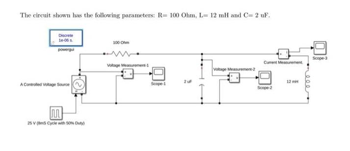
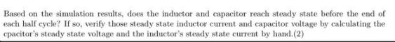
The circuit shown has the following parameters: R= 100 Ohm, L= 12 mH and C= 2 uF. Discrete 10-06 s powergui A Controlled Voltage Source M 25 V (m5 Cycle with 50% Duty) 100 Ohm Voltage Measurement-1 Scope-1 2 UF Voltage Measurement-2 Current Measurement Scope-2 12 mH Scope-3 Based on the simulation results, does the inductor and capacitor reach steady state before the end of each half cycle? If so, verify those steady state inductor current and capacitor voltage by calculating the cpacitor's steady state voltage and the inductor's steady state current by hand.(2)
Step by Step Solution
There are 3 Steps involved in it
Step: 1

Get Instant Access to Expert-Tailored Solutions
See step-by-step solutions with expert insights and AI powered tools for academic success
Step: 2

Step: 3
Ace Your Homework with AI
Get the answers you need in no time with our AI-driven, step-by-step assistance
Get Started
College Physics With An Integrated Approach To Forces And Kinematics
Authors: Alan Giambattista
5th Edition
126054771X, 978-1260547719