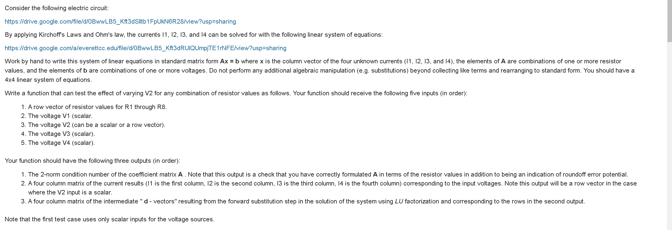
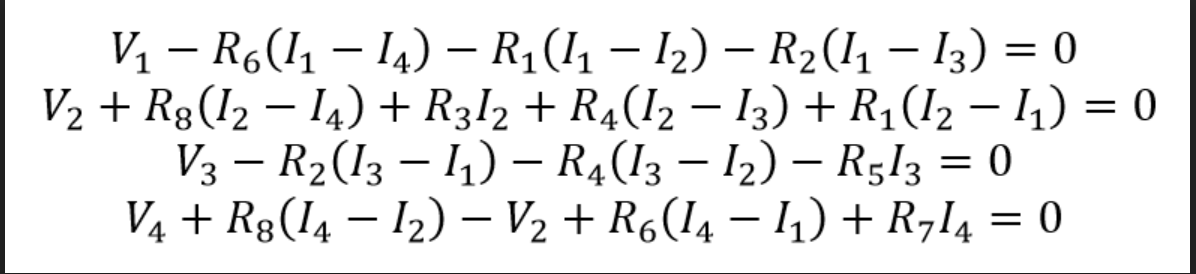

Consider the following electric circuit: https://drive.google.com/file/d/0BwWLB5_Kft3dSiltb1FpUkN6R28/view?usp=sharing By applying Kirchoff's Laws and Ohm's law, the currents 11, 12, 13, and 14 can be solved for with the following linear system of equations: https://drive.google.com/aleverettcc.edu/file/d/0BwwLB5_Kft3dRUIQUmpjTE1rNFE/view?usp=sharing Work by hand to write this system of linear equations in standard matrix form Ax = b where x is the column vector of the four unknown currents (11, 12, 13, and 14), the elements of A are combinations of one or more resistor values, and the elements of b are combinations of one or more voltages. Do not perform any additional algebraic manipulation (e.g. substitutions) beyond collecting like terms and rearranging to standard form. You should have a 4x4 linear system of equations. Write a function that can test the effect of varying V2 for any combination of resistor values as follows. Your function should receive the following five inputs (in order): 1. A row vector of resistor values for R1 through R8. 2. The voltage V1 (scalar. 3. The voltage V2 (can be a scalar or a row vector). 4. The voltage V3 (scalar). 5. The voltage V4 (scalar). Your function should have the following three outputs (in order): 1. The 2-norm condition number of the coefficient matrix A. Note that this output is a check that you have correctly formulated A in terms of the resistor values in addition to being an indication of roundoff error potential. 2. A four column matrix of the current results (11 is the first column, 12 is the second column, 13 is the third column, 14 is the fourth column) corresponding to the input voltages. Note this output will be a row vector in the case where the V2 input is a scalar. 3. A four column matrix of the intermediate "d - vectors" resulting from the forward substitution step in the solution of the system using LU factorization and corresponding to the rows in the second output. Note that the first test case uses only scalar inputs for the voltage sources. V1 R6(11 14) R1(11 12) R2(11 13) = 0 V2 + R$(12 14) + R312 + R4(12 13) + R1(12 11) = 0 V3 R2(13 11) R4(13 12) R513 = 0 V4 + R3(14 12) V2 + R6(14 11) + R714 = 0 function [condition_number, currents, d_vectors] student_solution(R_values, V1, V2, V3, 14) Consider the following electric circuit: https://drive.google.com/file/d/0BwWLB5_Kft3dSiltb1FpUkN6R28/view?usp=sharing By applying Kirchoff's Laws and Ohm's law, the currents 11, 12, 13, and 14 can be solved for with the following linear system of equations: https://drive.google.com/aleverettcc.edu/file/d/0BwwLB5_Kft3dRUIQUmpjTE1rNFE/view?usp=sharing Work by hand to write this system of linear equations in standard matrix form Ax = b where x is the column vector of the four unknown currents (11, 12, 13, and 14), the elements of A are combinations of one or more resistor values, and the elements of b are combinations of one or more voltages. Do not perform any additional algebraic manipulation (e.g. substitutions) beyond collecting like terms and rearranging to standard form. You should have a 4x4 linear system of equations. Write a function that can test the effect of varying V2 for any combination of resistor values as follows. Your function should receive the following five inputs (in order): 1. A row vector of resistor values for R1 through R8. 2. The voltage V1 (scalar. 3. The voltage V2 (can be a scalar or a row vector). 4. The voltage V3 (scalar). 5. The voltage V4 (scalar). Your function should have the following three outputs (in order): 1. The 2-norm condition number of the coefficient matrix A. Note that this output is a check that you have correctly formulated A in terms of the resistor values in addition to being an indication of roundoff error potential. 2. A four column matrix of the current results (11 is the first column, 12 is the second column, 13 is the third column, 14 is the fourth column) corresponding to the input voltages. Note this output will be a row vector in the case where the V2 input is a scalar. 3. A four column matrix of the intermediate "d - vectors" resulting from the forward substitution step in the solution of the system using LU factorization and corresponding to the rows in the second output. Note that the first test case uses only scalar inputs for the voltage sources. V1 R6(11 14) R1(11 12) R2(11 13) = 0 V2 + R$(12 14) + R312 + R4(12 13) + R1(12 11) = 0 V3 R2(13 11) R4(13 12) R513 = 0 V4 + R3(14 12) V2 + R6(14 11) + R714 = 0 function [condition_number, currents, d_vectors] student_solution(R_values, V1, V2, V3, 14)