Question
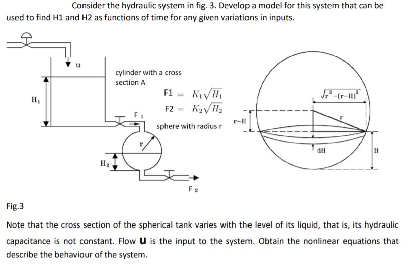
Consider the hydraulic system in fig. 3. Develop a model for this system that can be used to find H1 and H2 as functions

Consider the hydraulic system in fig. 3. Develop a model for this system that can be used to find H1 and H2 as functions of time for any given variations in inputs. cylinder with a cross section A F1 = KVH1 H1 F2 = K2VH2 %3D r-H sphere with radius r HP H2 F2 Fig.3 Note that the cross section of the spherical tank varies with the level of its liquid, that is, its hydraulic capacitance is not constant. Flow U is the input to the system. Obtain the nonlinear equations that describe the behaviour of the system.
Step by Step Solution
3.51 Rating (154 Votes )
There are 3 Steps involved in it
Step: 1

Get Instant Access to Expert-Tailored Solutions
See step-by-step solutions with expert insights and AI powered tools for academic success
Step: 2

Step: 3

Ace Your Homework with AI
Get the answers you need in no time with our AI-driven, step-by-step assistance
Get StartedRecommended Textbook for
Modern Control Systems
Authors: Richard C. Dorf, Robert H. Bishop
12th edition
136024580, 978-0136024583
Students also viewed these Mechanical Engineering questions
Question
Answered: 1 week ago
Question
Answered: 1 week ago
Question
Answered: 1 week ago
Question
Answered: 1 week ago
Question
Answered: 1 week ago
Question
Answered: 1 week ago
Question
Answered: 1 week ago
Question
Answered: 1 week ago
Question
Answered: 1 week ago
Question
Answered: 1 week ago
Question
Answered: 1 week ago
Question
Answered: 1 week ago
Question
Answered: 1 week ago
Question
Answered: 1 week ago
Question
Answered: 1 week ago
Question
Answered: 1 week ago
Question
Answered: 1 week ago
Question
Answered: 1 week ago
Question
Answered: 1 week ago
Question
Answered: 1 week ago
Question
Answered: 1 week ago
Question
Answered: 1 week ago
View Answer in SolutionInn App


