Question
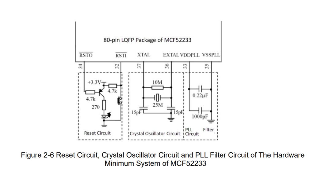
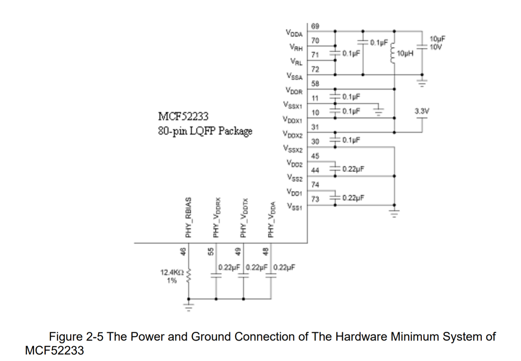
Consider the minimum hardware configuration of the MCF52233 described in the book, especially figures 2-5 and 2-6. What is the purpose of the inductor in
Consider the minimum hardware configuration of the MCF52233 described in the book, especially figures 2-5 and 2-6.
What is the purpose of the inductor in Figure 2-5?
In Figure 2-6, VDDPLL and VSSPLL have two capacitors in parallel attached to them. What is the ratio of the values of the two different capacitors? Why have capacitors of two different values been selected?
In Figure 2-6, what is the structure labeled 25M?
What is the purpose of the TDI and TDO pins on the debug header?
When testing a board for the first time, if the board does not work, what is always the first thing to check?


Step by Step Solution
There are 3 Steps involved in it
Step: 1

Get Instant Access to Expert-Tailored Solutions
See step-by-step solutions with expert insights and AI powered tools for academic success
Step: 2

Step: 3

Ace Your Homework with AI
Get the answers you need in no time with our AI-driven, step-by-step assistance
Get Started


